


CHAPTER 2 V
R
4120A
Preliminary User’s Manual S15543EJ1V0UM
169
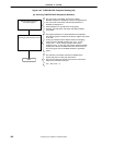
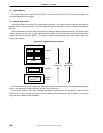
2.7.2 Cache organization
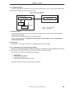
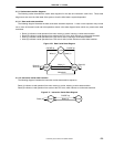
This section describes the organization of the on-chip data and instruction caches. Figure 2-66 provides a block
diagram of the V
R
4120A Core cache and memory model.
Figure 2-66. Cache Support
V
R
4120A CPU core
Cache controller
I-cache
D-cache
Caches
Main memory
I-cache: Instruction cache
D-cache: Data cache
(1) Cache line lengths
A cache line is the smallest unit of information that can be fetched from main memory for the cache, and that is
represented by a single tag.
The line size for the instruction/data cache is 4 words (16 bytes).
For the cache tag, see 2.7.2.1 Organization of the instruction cache (I-cache) and 2.7.2.2 Organization of
the data cache (D-cache).
(2) Cache sizes
The instruction cache in the V
R
4120A Core is 16 Kbytes; the data cache is 8 Kbytes.
2.7.2.1 Organization of the instruction cache (I-cache)
Each line of I-cache data (although it is actually an instruction, it is referred to as data to distinguish it from its tag)
has an associated 23-bit tag that contains a 22-bit physical address, and a single valid bit.
The V
R
4120A Core I-cache has the following characteristics:
direct-mapped
indexed with a virtual address
checked with a physical tag
organized with a 4-word (16-byte) cache line
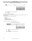
Figure 2-67 shows the format of a 4-word (16-byte) I-cache line.