


CHAPTER 2 V
R
4120A
Preliminary User’s Manual S15543EJ1V0UM
87
2.3.2 Branch delay
During a V
R
4120A's pipeline operation, a one-cycle branch delay occurs when:
• Target address is calculated by a Jump instruction
• Branch condition of branch instruction is met and then logical operation starts for branch-destination
comparison
The instruction location following the Jump/Branch instruction is called a branch delay slot.
The instruction address generated at the EX stage in the Jump/Branch instruction are available in the IF stage, two
instructions later. In MIPS III instruction mode, branch delay is two cycles. One instruction in the branch delay slot is
executed, except for likely instruction.
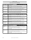
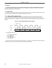
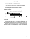
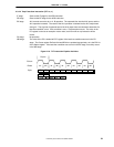
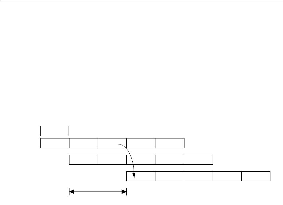
Figure 2-12 illustrates the branch delay and the location of the branch delay slot during MIPS III instruction mode.
Figure 2-12. Branch Delay (In MIPS III Instruction Mode)
(Branch delay slot)
Target
Branch
Branch delay
PCycle
IF RF EX DC WB
IF RF EX DC WB
IF RF EX DC WB
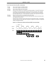
2.3.3 Load delay
In the case of a load instruction, 2 cycles are required for the DC stage, for reading from the data cache and
performing data alignment. In this case, the hardware automatically generates on interlock.
A load instruction that does not allow its result to be used by the instruction immediately following is called a
delayed load instruction. The instruction immediately following this delayed load instruction is referred to as the load
delay slot.
In the V
R
4120A, the instruction immediately following a load instruction can use the contents of the loaded register,
however in such cases hardware interlocks insert additional delay cycles. Consequently, scheduling load delay slots
can be desirable, both for performance and V
R
-Series processor compatibility.