


CHAPTER 6 USB CONTROLLER
350
Preliminary User’s Manual S15543EJ1V0UM
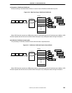
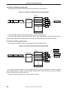
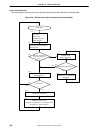
(3) EndPoint2, EndPoint4, assemble mode
The processing in EndPoint2, EndPoint4 receive Assemble mode is explained below.
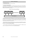
Figure 6-18. EndPoint2, EndPoint4 Receive Assemble Mode
D0
µ
PD98502
Buffer
Directory
D1D2
D1
D2
D2
Rx Indication
D0
D0
D1
D3
D3
In this mode USB Controller issues Rx indication after receiving one data segment.
In other word, after USB Controller writes the Short packet or Zero-Length Packet received from USB to buffer in
system memory, USB Controller updates Size field, Last bit in last Buffer Descriptor and issues Rx indication.
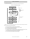
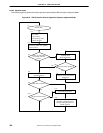
(4) EndPoint2, EndPoint4, separate mode
The processing in EndPoint2, EndPoint4 receive separate mode is explained below.
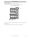
Figure 6-19. EndPoint2, EndPoint4 Receive Separate Mode
D0
µ
PD98502
Buffer
Directory
D1D2
D1
D2
D2
Rx Indication
Rx Indication
Rx Indication
Rx Indication
D0
D0
D1
D2
In this mode, after USB Controller receives USB packet and stores the data in Rx buffer, it issues Rx indication
when a buffer is full. Even if a buffer is full in the middle of USB packets, it issues indication. After that, processing of
storing the USB packet to next buffer continues.
It does not execute to update Size field, Last bit in Buffer Descriptor.