


APPENDIX A MIPS III INSTRUCTION SET DETAILS
432
Preliminary User’s Manual S15543EJ1V0UM
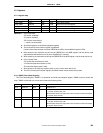
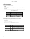
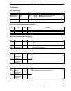
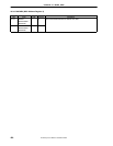
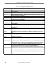
Table A-1. CPU Instruction Operation Notations
Symbol Description
← Assignment
|| Bit string concatenation
x
y
Replication of bit value
x
into a
y
-bit string.
x
is always a single-bit value
xy:z Selection of bits
y
through
z
of bit string
x
. Little-endian bit notation is always used. If
y
is less than
z
, this
expression is an empty (zero length) bit string
+2’s complement or floating-point addition
-2’s complement or floating-point subtraction
*2’s complement or floating-point multiplication
div 2’s complement integer division
mod 2’s complement modulo
/ Floating-point division
<2’s complement less than comparison
and Bit-wise logical AND
or Bit-wise logical OR
xor Bit-wise logical XOR
nor Bit-wise logical NOR
GPR [
x
] General-Register
x
. The content of GPR [0] is always zero. Attempts to alter the content of GPR [0] have no
effect.
CPR [
z, x
] Coprocessor unit
z
, general register
x
.
CCR [
z, x
] Coprocessor unit
z
, control register
x
.
COC [
z
] Coprocessor unit
z
condition signal.
BigEndianMem Big-endian mode as configured at reset (0 → Little, 1 → Big). Specifies the endianness of the memory interface
(see LoadMemory and StoreMemory), and the endianness of Kernel and Supervisor mode execution. However,
this value is always 0 since the V
R
4120A CPU supports the little endian order only.
ReverseEndian Signal to reverse the endianness of load and store instructions. This feature is available in User mode only, and
is effected by setting the RE bit of the Status register. Thus, ReverseEndian may be computed as (SR25 and
User mode).However, this value is always 0 since the V
R
4120A CPU supports the little endian order only.
BigEndianCPU The endianness for load and store instructions (0 → Little, 1 → Big). In User mode, this endianness may be
reversed by setting RE bit. Thus, BigEndianCPU may be computed as BigEndianMem XOR
ReverseEndian.However, this value is always 0 since the V
R
4120A CPU supports the little endian order only.
T +
i
: Indicates the time steps between operations. Each of the statements within a time step are defined to be
executed in sequential order (as modified by conditional and loop constructs). Operations which are marked T +
i
: are executed at instruction cycle
i
relative to the start of execution of the instruction. Thus, an instruction which
starts at time
j
executes operations marked T +
i:
at time
i + j
. The interpretation of the order of execution
between two instructions or two operations that execute at the same time should be pessimistic; the order is not
defined.