


20
Preliminary User’s Manual S15543EJ1V0UM
LIST OF FIGURES (5/5)
Figure No. Title Page
6-16 Data Receiving in EndPoint0, EndPoint6.....................................................................................................349
6-17 EndPoint2, EndPoint4 Receive Normal Mode..............................................................................................349
6-18 EndPoint2, EndPoint4 Receive Assemble Mode .........................................................................................350
6-19 EndPoint2, EndPoint4 Receive Separate Mode...........................................................................................350
6-20 VR
4120A Receive Processing......................................................................................................................351
6-21 USB Controller Receive Operations (Normal Mode)....................................................................................352
6-22 USB Controller Receive Operations (Assemble Mode)................................................................................354
6-23 USB Controller Receive Operation Sequence (Separate Mode)..................................................................356
6-24 USB Timing Errors.......................................................................................................................................358
6-25 Example of Buffers Including Corrupted Data..............................................................................................361
6-26 Receive Indication Format ...........................................................................................................................362
6-27 Suspend Sequence......................................................................................................................................364
6-28 Resume Sequence ......................................................................................................................................365
6-29 Remote Wake Up Sequence........................................................................................................................366
6-30 Allowable Skew for SOF ..............................................................................................................................367
6-31 Data Flow in Loopback Mode.......................................................................................................................368
6-32 Example of Connection................................................................................................................................369
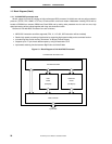
7-1 The PCI Controller Block Diagram...............................................................................................................370
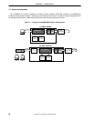
7-2 Posted Write Transaction from Internal Bus to PCI......................................................................................372
7-3 Non Posted Write Transaction from Internal Bus to PCI..............................................................................373
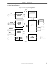
7-4 Delayed Read Transaction from Internal Bus to PCI ...................................................................................374
7-5 Non Delayed Read Transaction from Internal Bus to PCI............................................................................375
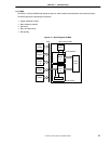
7-6 Posted Write Transaction from PCI to Internal bus......................................................................................377
7-7 Non Posted Write Transaction from PCI to Internal bus ..............................................................................378
7-8 Delayed Read Transaction from PCI to Internal bus....................................................................................379
7-9 Non Delayed Read Transaction from PCI to Internal bus ............................................................................380
7-10 The Sequence of the Transition by Issues from PCI-Host ...........................................................................384
7-11 The Sequence of the Transition by PME......................................................................................................385
7-12 The Content of P_PCAR Register for Type0 Configuration Cycle ...............................................................386
7-13 The Content of P_PCAR Register for Type1 Configuration Cycle ...............................................................386
7-14 An Example How to Connect AD [31:16] Signal Line to IDSEL Port............................................................388
7-15 Address Stepping for IDSEL........................................................................................................................388
7-16 Arbitration in Alternating Mode.....................................................................................................................389
7-17 Arbitration in Rotating Mode.........................................................................................................................389
A-1 V
R
4120A Opcode Bit Encoding....................................................................................................................588