


CHAPTER 8 UART
Preliminary User’s Manual S15543EJ1V0UM
421
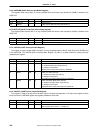
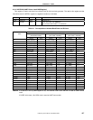
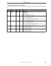
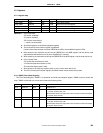
8.3.10 UARTMCR (UART Modem Control Register)
This register controls the state of external URDTR_B and URRTS_B modem-control signals and of the loop-back
test.
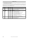
Bits Field R/W Default Description
31:5 Reserved R/W 0 Hardwired to 0.
4 LOOP R/W 0 Loop-Back Test.
1 = loop-back.
0 = normal operation.
This is an NEC internal test function.
3 OUT2 R/W 0 Out 2 (internal signal).
1 = OUT2_B (internal) state active.
0 = OUT2_B (internal) state inactive (reset value).
This is a user-defined bit that has no associated external signal. Software
can write to the bit, but this has no effect.
2 OUT1 R/W 0 Out 1 (internal signal).
1 = OUT1_B (internal) state active.
0 = OUT1_B (internal) state inactive (reset value).
This is a user-defined bit that has no associated external signal. Software
can write to the bit, but this has no effect.
1 RTS R/W 0 Request To Send.
1 = negate URRTS_B signal.
0 = assert URRTS_B signal.
0 DTR R/W 0 Data Terminal Ready.
1 = negate URDTR_B signal.
0 = assert URDTR_B signal.