


CHAPTER 3 SYSTEM CONTROLLER
Preliminary User’s Manual S15543EJ1V0UM
191
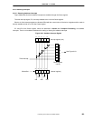
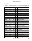
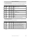
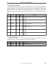
3.2.2 S_GMR (General Mode Register)
The general mode register “S_GMR” is a read-write and 32-bit word-aligned register. After initializing, V
R
4120A
sets the IAEN bit to enable the IBUS arbiter. S_GMR is initialized to 0 at reset and contains the following fields:
Bits Field R/W Default Description
31:10 Reserved R/W 0 Hardwired to 0.
9 MSWP R/W 0 MIF block data swap function enable:
0 = disable
1 = enable
8 HSWP R/W 0 HIF block data swap function enable:
0 = disable
1 = enable
7:4 Reserved R/W 0 Hardwired to 0.
3 UCSEL R/W 0 UART source clock selection:
0 = use 1/2 of CPU clock
1 = use external clock (18.432 MHz)
2 MPFD R/W 0 Memory-to-CPU prefetch FIFO disable:
0 = enable
1 = disable
1 IAEN R/W 0 IBUS arbiter enable:
0 = disable (IBUS arbiter does not allow the grant except system controller)
1 = enable.
0 CRST R/W 0 Cold reset:
0 = do nothing
1 = perform cold reset (same as hardware system reset)
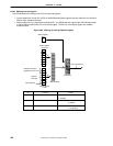
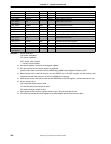
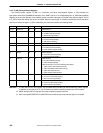
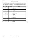
3.2.3 S_GSR (General Status Register)
The general status register “S_GSR” is a read-only and 32-bit word-aligned register. S_GSR indicates the status of
external pins of the
µ
PD98502. S_GSR contains the following fields:
Bits Field R/W Default Description
31:3 Reserved R 0 Hardwired to 0.
2 MIPS16 R - Reflects the status of external pin “MIPS16” after reset:
This field indicates the same value as M16 bit of CPU configuration register.
0 = connected to GND, that means MIPS16 mode is disabled NOTE.
1 = connected to VCC, that means MIPS16 mode is enabled.
1 CLKSL R - Reflects the status of external pin “CLKSL” after reset:
0 = connected to GND, that means CPU is operated at 100 MHz.
1 = connected to VCC, that means CPU is operated at 66 MHz.
0 ENDCEN R - Reflects the status of external pin “ENDCEN” after reset:
0 = connected to GND, that means Endian Converter is disabled.
1 = connected to VCC, that means Endian Converter is enabled.
NOTE The
µ
PD98502 does not support MIPS16 mode. MIPS16 mode pin (located D11) should be connected to
GND.