


CHAPTER 2 V
R
4120A
98
Preliminary User’s Manual S15543EJ1V0UM
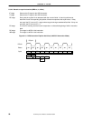
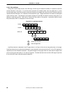
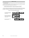
2.3.5.3 Slip conditions
During
Φ
2 of the RF stage and Φ1 of the EX stage, internal logic will determine whether it is possible to start the
current instruction in this cycle. If all of the source operands are available (either from the register file or via the
internal bypass logic) and all the hardware resources necessary to complete the instruction will be available whenever
required, then the instruction “run”; otherwise, the instruction will “slip”. Slipped instructions are retired on subsequent
cycles until they issue. The backend of the pipeline (stages DC and WB) will advance normally during slips in an
attempt to resolve the conflict. NOPs will be inserted into the bubble in the pipeline. Instructions killed by branch
likely instructions, ERET or exceptions will not cause slips.
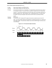
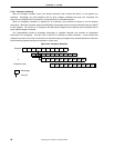
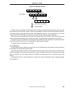
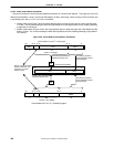
Figure 2-23. Load Data Interlock
1
ADD A,B
Load B
Load A
Bypass
Detect load interlock
IF RF EX DC WB
IF RF EX DC WB
IF RF RF EX DC WB
IF RF EX DC WB
1
Get the target data2
2
Load Data Interlock is detected in the RF stage shown in as Figure 2-23 and also the pipeline slips in the stage.
Load Data Interlock occurs when data fetched by a load instruction and data moved from HI, LO or CP0 registers is
required by the next immediate instruction. The pipeline begins running again when the clock after the target of the
load is read from the data cache, HI, LO and CP0 registers. The data returned at the end of the DC stage is input into
the end of the RF stage, using the bypass multiplexers.