


CHAPTER 2 V
R
4120A
64
Preliminary User’s Manual S15543EJ1V0UM
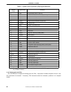
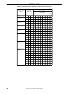
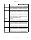
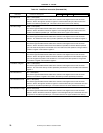
Table 2-1. System Control Coprocessor (CP0) Register Definitions
Register
Number
Register Name Description
0 Index Programmable pointer to TLB array
1 Random Pseudo-random pointer to TLB array (read only)
2 EntryLo0 Low half of TLB entry for even VPN
3 EntryLo1 Low half of TLB entry for odd VPN
4 Context Pointer to kernel virtual PTE in 32-bit mode
5 PageMask TLB page mask
6 Wired Number of wired TLB entries
7 Reserved for future use
8 BadVAddr Virtual address where the most recent error occurred
9 Count Timer count
10 EntryHi High half of TLB entry (including ASID)
11 Compare Timer compare
12 Status Status register
13 Cause Cause of last exception
14 EPC Exception Program Counter
15 PRId Processor revision identifier
16 Config Configuration register (specifying memory mode system)
17 LLAddr Reserved for future use
18 WatchLo Memory reference trap address low bits
19 WatchHi Memory reference trap address high bits
20 XContext Pointer to kernel virtual PTE in 64-bit mode
21 to 25 Reserved for future use
26
PErr
Note
Cache parity bits
27
CacheErr
Note
Index and status of cache error
28 TagLo Cache Tag register (low)
29 TagHi Cache Tag register (high)
30 ErrorEPC Error Exception Program Counter
31 Reserved for future use
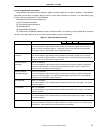
Note This register is defined to maintain compatibility with the VR
4100™. This register is not used in
the
µ
PD98502 hardware.
2.1.6 Floating-point unit (FPU)
The V
R
4120A does not support the floating-point unit (FPU). Coprocessor Unusable exception will occur if any
FPU instructions are executed. If necessary, FPU instructions should be emulated by software in an exception
handler.