


E6580757
F-29
6
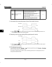
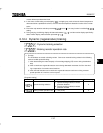
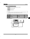
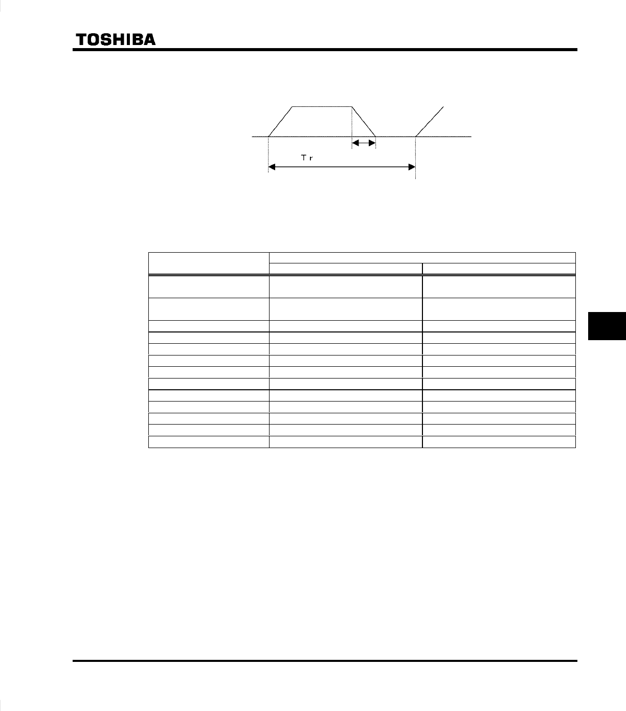
2) Setting the braking resistor operation rate
Calculate the braking resistor operation rate as follows:
Braking resistor
o
p
eratin
g
time
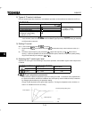
Operation rate: Tr/T * 100 (%ED)
1-cycle operation time T
3) Optional dynamic braking resistors (Optional braking resistors for higher frequen-
cies of regenerative braking are also available)
Optional dynamic braking resistors are listed below. All these resistors are 3%ED in operation rate.
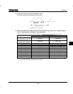
Braking resistor/Braking unit
Inverter model
Model number Rating
VFS9S-2002PL ∼ 2007PL
VFS9-2002PM ∼ 2007PM
PBR-2007
120W- 200Ω
VFS9S-2015PL ∼ 2022PL
VFS9-2015PM ∼ 2022PM
PBR-2022
120W- 75Ω
VFS9-2037PM PBR-2037
120W- 40Ω
VFS9-2055PL PBR3-2055
120W- 40Ω × 2P (240W- 20Ω)
VFS9-2075PL PBR3-2075
220W- 30Ω × 2P (440W- 15Ω)
VFS9-2110PM PBR3-2110
220W- 30Ω × 3P (660W- 10Ω)
VFS9-2150PM PBR3-2150
220W- 30Ω × 4P (880W- 7.5Ω)
VFS9-4007PL ∼ 4022PL
PBR-2007
120W- 200Ω
VFS9-4037PL PBR-4037
120W-160Ω
VFS9-4055PL PBR3-4055
120W-160Ω × 2P (240W- 80Ω)
VFS9-4075PL PBR3-4075
220W-120Ω × 2P (440W- 60Ω)
VFS9-4110PL PBR3-4110
220W-120Ω × 3P (660W- 40Ω)
VFS9-4150PL PBR3-4150
220W-120Ω × 4P (880W- 30Ω)
Note: The data in parentheses above refer to the resultant resistance capacities (watts) and resultant resis-
tance values (ohms) of standard braking resistors.