


E6580757
B-4
2
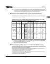
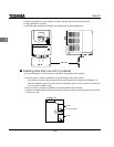
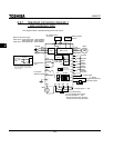
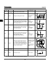
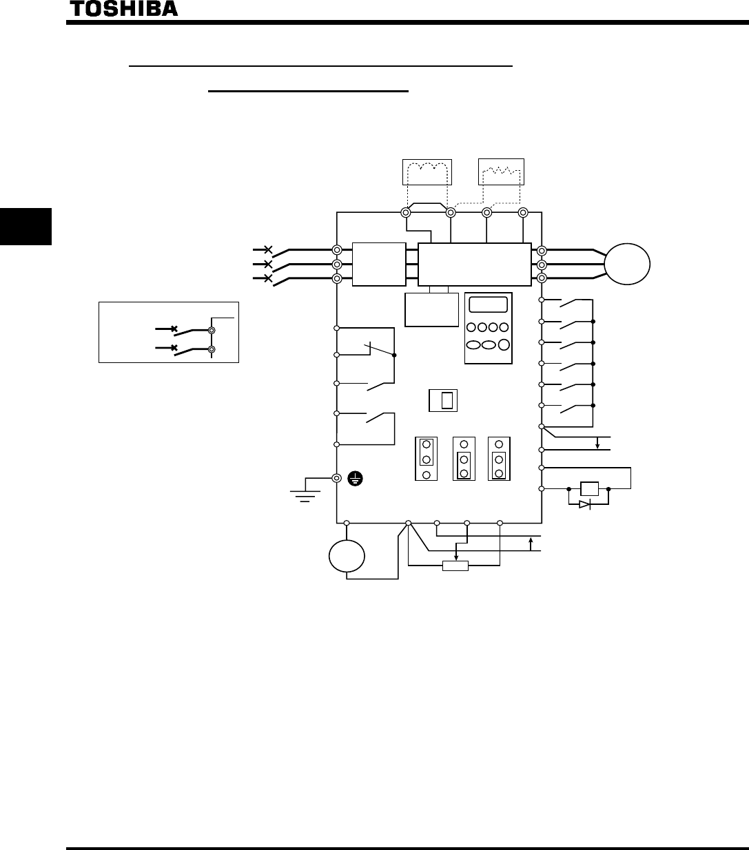
2.2.1 Standard connection diagram 1
- sink (common: CC)
This diagram shows a standard wiring of the main circuit.
MCCB
R/L1
S/L2
*1
U/T1
V/T2
W/T3
FLC
FLB
FLA
RY
RC
F
R
RST
S1
S2
S3
CC
I I
P24
OUT
FM
CC
VIA
VIB
PP
+
+
+
-
-
P0 PA PB PC
Ry
VF-S9
MCCB(2P)
R/L1
S/L2
JP301
JP301A
JP302
DC reactor (DCL)
*2 (option)
Braking resistor
(option)
Main circuitFilter
Main circuit power supply
200V class: single-phase 200 ~ 240V-50/60Hz
three-phase 200 ~ 230V-50/60Hz
400V class: three-phase 380 ~ 500V-50/60Hz
Motor
Operation panel
Control
circuit
Meter
Forward
Fault detection
relay
Low-speed
detection signal
Reverse
Reset
Preset
speed2
Preset
speed1
Frequency
meter
Preset
speed3
Current signal:
4 ~ 20mA
Voltage signal: 0 ~ 10V
External potentiometer
(or input voltage signal across
VIA-CC terminals: 0 ~ 10V)
*The VIA terminal and II terminal
cannot be used at the same time.
*1 1-phase series don't have T/L3 terminal.
*2 The PO-PA terminals are shorted by
a bar when shipped from the factory.
Before installing the DC reactor (DCL),
remove the bar.
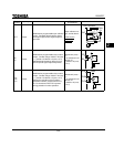
FMC
SINK
SOURCE
FMV
Connector for
common serial
communications
Power supply
1φ200 ~ 240V
-50/60Hz
IM
Common
Designated frequency
attainment signal
T/L3