


E6580757
J-1
10
10. Peripheral devices
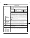
Danger
Danger
Mandatory
• When using switchgear for the inverter, it must be installed in a cabinet.
Failure to do so can lead to risk of electric shock and can result in death or serious injury.
Be Grounded
• Connect earth cables securely. Failure to do so can lead to risk of electric shock or fire in case of a
failure, short-circuit or leak current.
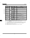
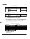
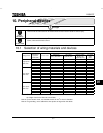
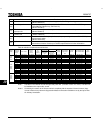
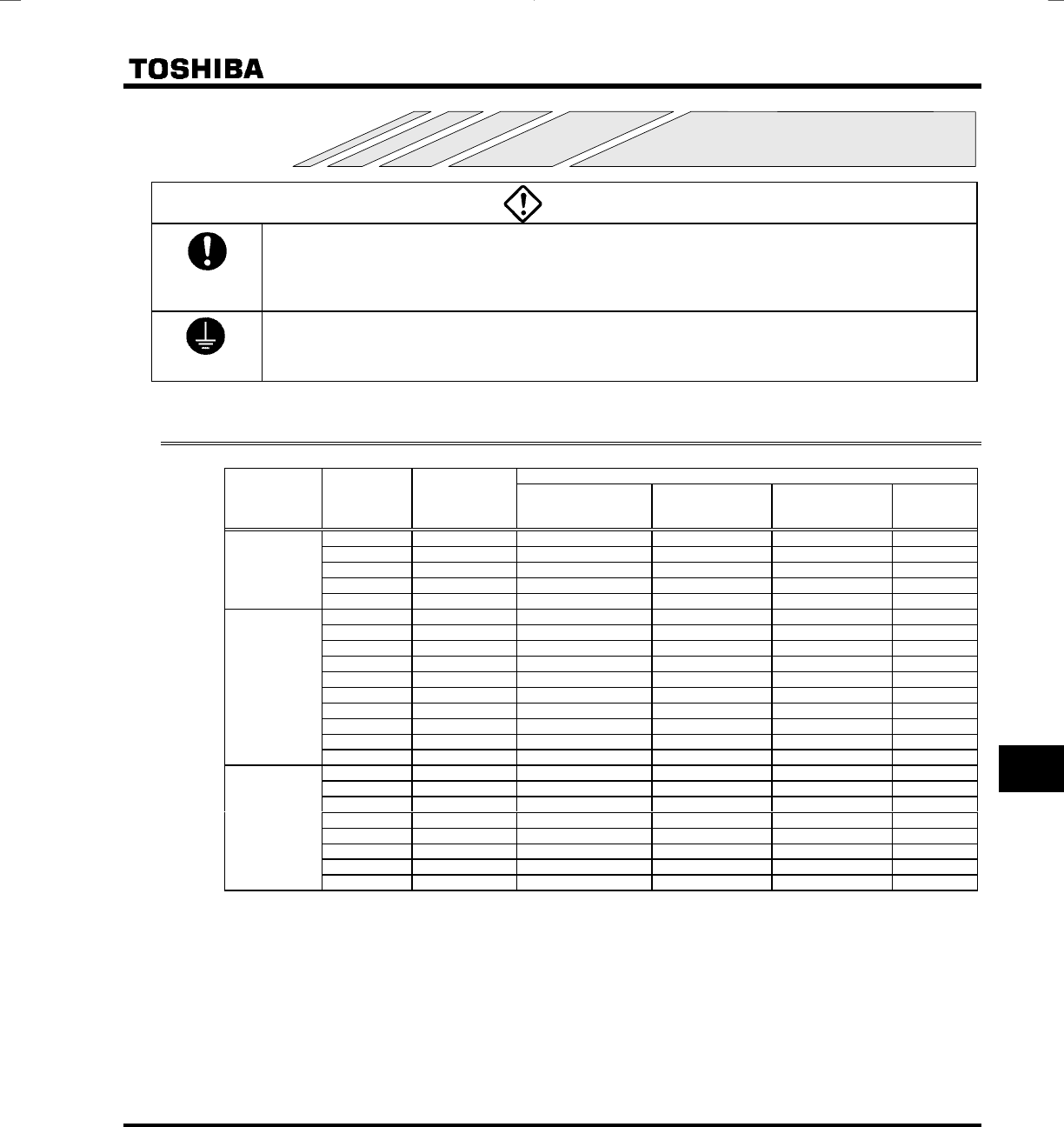
10.1 Selection of wiring materials and devices
Wire size
Voltage class
Capacity of
applicable
motor (kW)
Inverter model
Main circuit
(mm
2
) (See Note 1.)
DC reactor
(optional) (mm
2
)
Braking resistor/
Braking unit
(optional) (mm
2
)
Grounding
cable
(mm
2
)
0.2 VFS9S-2002PL 2.0 1.25 1.25 3.5
0.4 VFS9S-2004PL 2.0 1.25 1.25 3.5
0.75 VFS9S-2007PL 2.0 2.0 1.25 3.5
1.5 VFS9S-2015PL 3.5 2.0 1.25 3.5
Single-phase
200V class
2.2 VFS9S-2022PL 5.5 2.0 2.0 5.5
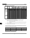
0.2 VFS9-2002PM 2.0 1.25 1.25 3.5
0.4 VFS9-2004PM 2.0 1.25 1.25 3.5
0.75 VFS9-2007PM 2.0 2.0 1.25 3.5
1.5 VFS9-2015PM 2.0 2.0 1.25 3.5
2.2 VFS9-2022PM 2.0 2.0 2.0 3.5
3.7 VFS9-2037PM 3.5 5.5 5.5 3.5
5.5 VFS9-2055PL 8.0 5.5 5.5 8.0
7.5 VFS9-2075PL 14 14 5.5 14
11 VFS9-2110PM 14 14 5.5 14
Three-phase
200V class
15 VFS9-2150PM 22 22 5.5 22
0.75 VFS9-4007PL 2.0 1.25 1.25 3.5
1.5 VFS9-4015PL 2.0 1.25 1.25 3.5
2.2 VFS9-4022PL 2.0 2.0 1.25 3.5
3.7 VFS9-4037PL 2.0 2.0 1.25 3.5
5.5 VFS9-4055PL 3.5 2.0 2.0 3.5
7.5 VFS9-4075PL 3.5 3.5 2.0 5.5
11 VFS9-4110PL 5.5 5.5 3.5 8.0
Three-phase
400V class
15 VFS9-4150PL 8.0 8.0 3.5 8.0
Note 1: Sizes of the wires connected to the input terminals R, S and T and the output terminals U, V and W when
the length of each wire does not exceed 30m.
Note 2: For the control circuit, use shielded wires 0.75 mm
2
or more in diameter.
Note 3: For grounding, use a cable with a size equal to or larger than the above.