E6580757
A-19
1
Note: Do not install in any location where there is high humidity or high temperatures and where there are
large amounts of dust, metallic fragments and oil mist. If you are going to install the equipment in any
area that presents a potential problem, please consult with Toshiba before doing so.
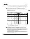
■ Calorific values of the inverter and the required ventilation
The energy loss when the inverter converts power from AC to DC and then back to AC is about 5 percent. In
order to suppress the rise in temperature inside the cabinet when this loss becomes heat loss, the interior of
the cabinet must be ventilated and cooled.
The amount of forcible air cooling ventilation required and the necessary heat discharge surface quantity
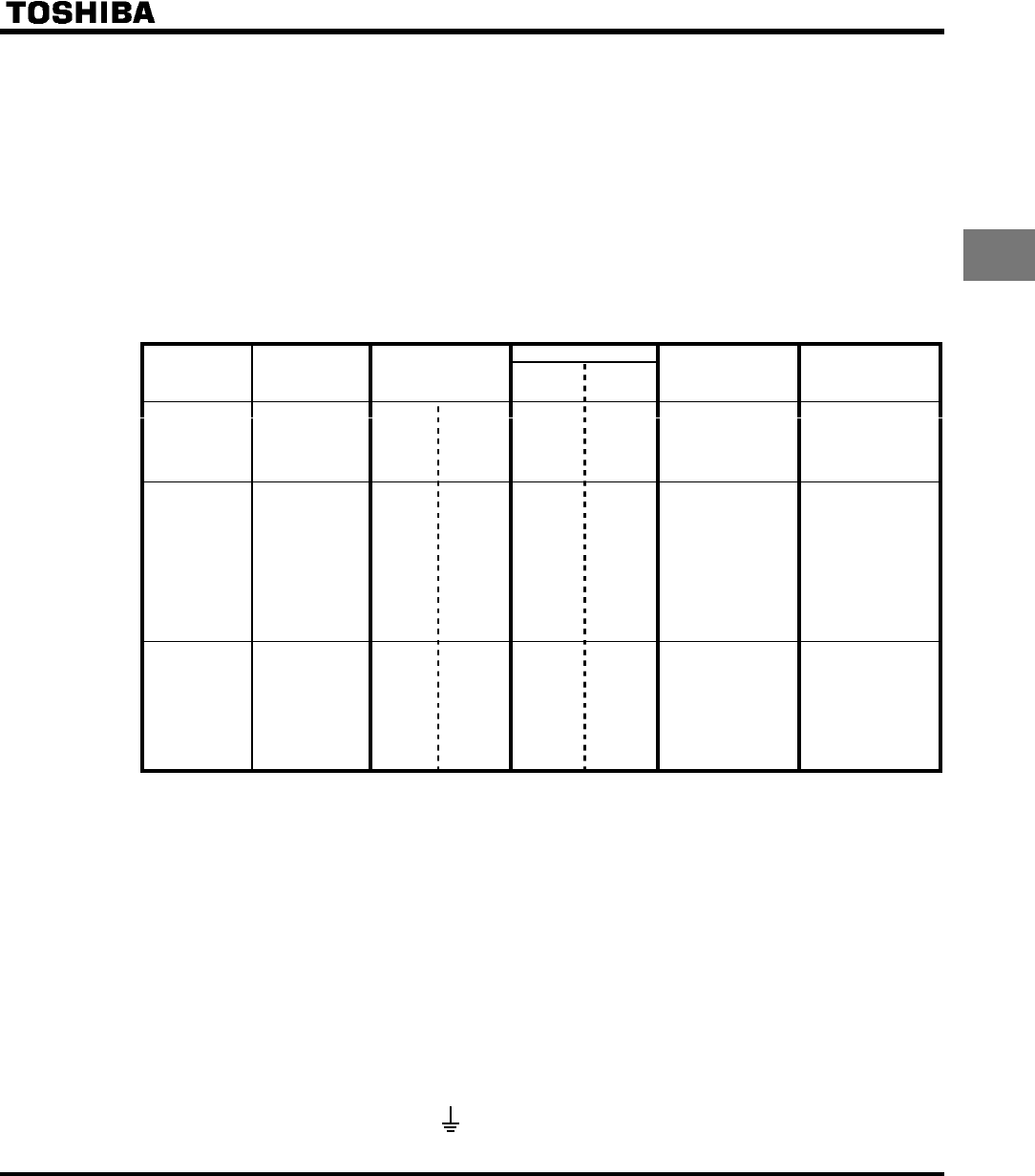
when operating in a sealed cabinet according to motor capacity are as follows.
Calorific Values
Voltage Class
Operating motor
capacity
(kW)
Inverter Type
Carrier
frequency
4kHz
Carrier
frequency
12kHz
Amount of forcible air
cooling ventilation re-
quired (m
3
/min)
Heat discharge surface
area required for sealed
storage cabinet(m
2
)
0.2 2002PL 23 29 0.23 0.8
0.4 2004PL 47 60 0.29 1.0
0.75 2007PL 74 88 0.40 1.4
1.5 2015PL 142 169 0.60 2.1
Single-Phase
200V Class
2.2
VFS9S-
2022PL 239 270 0.80 2.8
0.2 2002PM 21 26 0.23 0.8
0.4 2004PM 43 54 0.29 1.0
0.75 2007PM 67 79 0.40 1.4
1.5 2015PM 131 150 0.60 2.1
2.2 2022PM 168 195 0.80 2.8
3.7 2037PM 330 374 1.2 4.3
5.5 2055PL 450 510 1.7 6.1
7.5 2075PL 576 635 2.3 8.1
11 2110PM 750 820 3.4 12.0
Single-Phase
200V Class
15
VFS9-
2150PM 942 1035 4.6 16.0
0.75 2007PL 44 57 0.40 1.4
1.5 2015PL 77 99 0.60 2.1
2.2 2022PL 103 134 0.80 2.8
3.7 2037PL 189 240 1.2 4.3
5.5 2055PL 264 354 1.7 6.1
7.5 2075PL 358 477 2.3 8.1
11 2110PL 490 650 3.4 12.0
Three-Phase
400V Class
15
VFS9-
2150PL 602 808 4.6 16.0
Notes
1) The heat loss for the optional external devices (input reactor, DC reactor, radio noise reduction filters,
etc.) is not included in the calorific values in the table.
2) Case of 100% Load Continuation operation.
■ Panel designing taking into consideration the effects of noise.
The inverter generates high frequency noise. When designing the control panel setup, consideration must be
given to that noise. Examples of measures are given below.
• Wire so that the main circuit wires and the control circuit wires are separated. Do not place them in the
same conduit, do not run them parallel, and do not bundle them.
• Provide shielding and twisted wire for control circuit wiring.
• Separate the input (power) and output (motor) wires of the main circuit. Do not place them in the same
conduit, do not run them parallel, and do not bundle them.
• Ground the inverter ground terminals (
).


