


E6580757
C-5
3
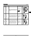
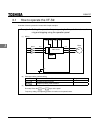
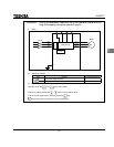
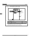
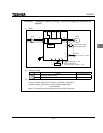
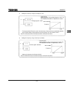
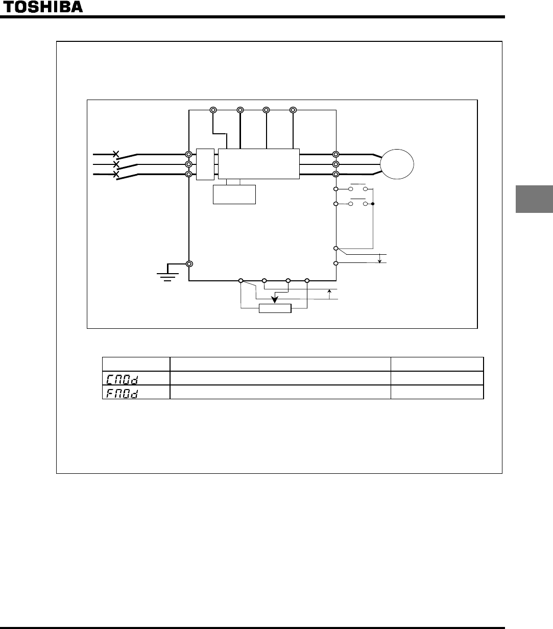
Example 4 Operation frequency setting, running and stopping using external
signals.
(1) Wiring
IM
F
R/L1
S/L2
T/L3
U/T1
V/T2
W/T3
R
PO PC
PB
PA
MCCB
CC
II
G
CC
VIB
VIA PP
Main circuit
Control
circuit
Reverse rotation signal
Common
Motor
Forward rotation signal
Current signal: 4 ∼ 20mA
Voltage signal: 0 ∼ 10V
External potentiometer
(or voltage signal to VIA-CC 0 ∼ 10V)
(2) Parameter setting
Title Function Programmed value
Command mode selection 0
Frequency setting mode selection 0
(3) Operation
Run/stop: ON/OFF input to F-CC and R-CC. (Set JP301 to Sink logic.)
Frequency setting: VIA and VIB: 0-10Vdc (external potentiometer)
II : Input 4-20mAdc.
Note) The VIA terminal and II terminal cannot be used at the same time.