


E6580757
A-12
1
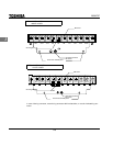
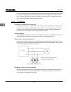
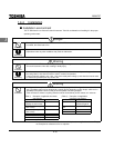
ured in some other way, the overcurrent trip may be activated because of the locked rotor current when
the brake goes into operation. Circuit configuration 2 uses low-speed signal RY to turn on and off the
brake. Turning the brake on and off with a low-speed signal may be better in such applications as ele-
vators. Please confer with us before designing the system.
1.4.2 Inverters
Protecting inverters from overcurrent
The inverter has an overcurrent protection function. However because the programmed current level is
set to the inverter's maximum applicable motor, if the motor is one of small capacity and it is in opera-
tion, the overcurrent level and the electronic thermal protection must be readjusted. If adjustment is
necessary, see 5-14 in Chapter 5, and make adjustments as directed.
Inverter capacity
Do not operate a large capacity motor with a small capacity (kVA) inverter even with light loads. Current
ripple will raise the output peak current making it easier to set off the overcurrent trip.
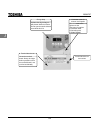
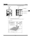
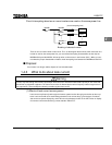
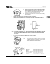
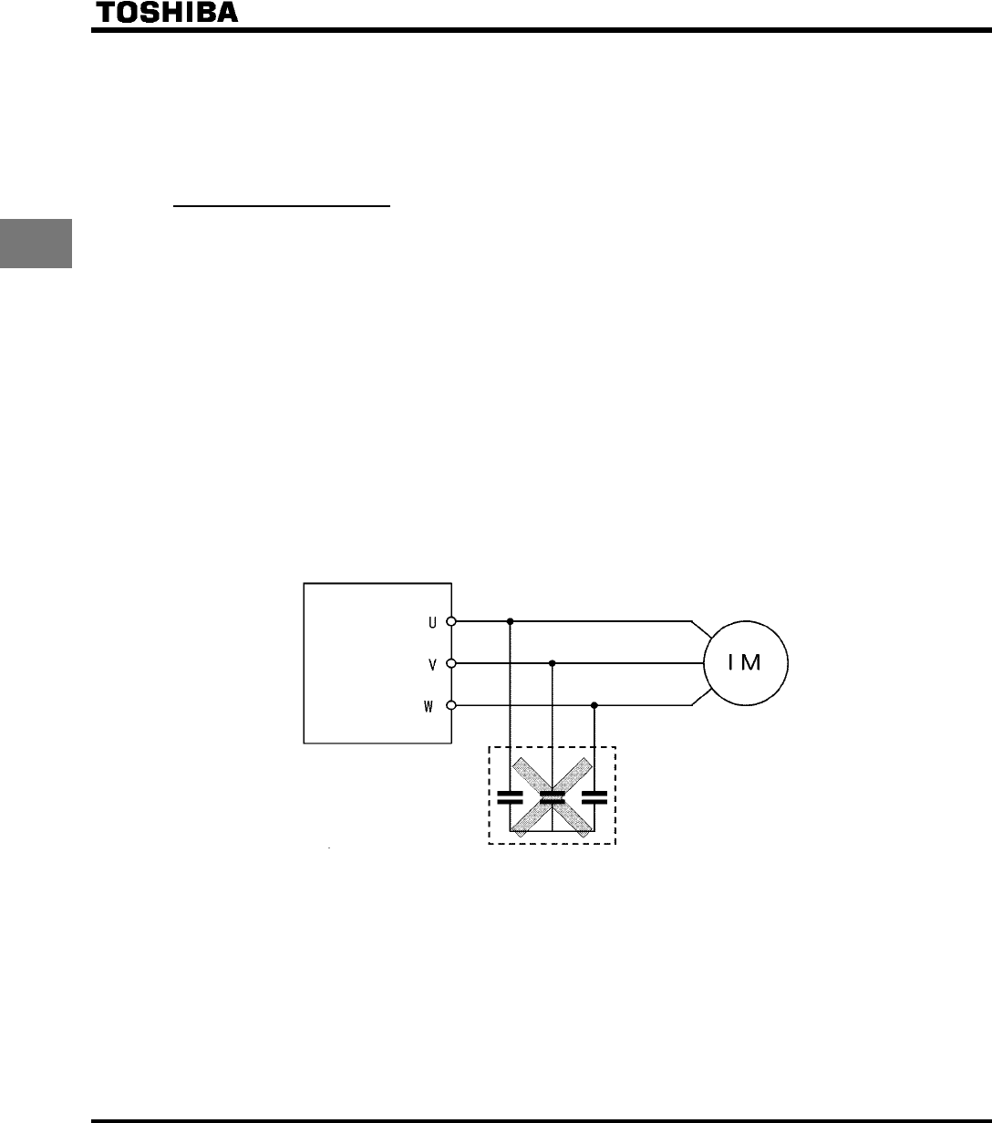
Power factor improving capacitors
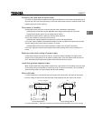
Power factor improving capacitors cannot be installed on the output side of the inverter. When a motor
is run that has a power factor improving capacitor attached to it, remove the capacitors. This can cause
inverter malfunction trips and capacitor destruction.
Inverter
Power factor improving capacitor
Remove the power factor improving
capacitor and surge absorber
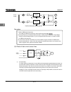
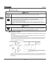
Operating at other than rated voltage
Connections to voltages other than the rated voltage described in the rating label cannot be made. If a
connection must be made to a power supply other than one with rated voltage, use a transformer to
raise or lower the voltage to the rated voltage.