E6580757
F-2
6
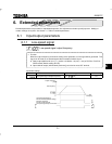
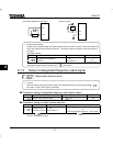
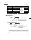
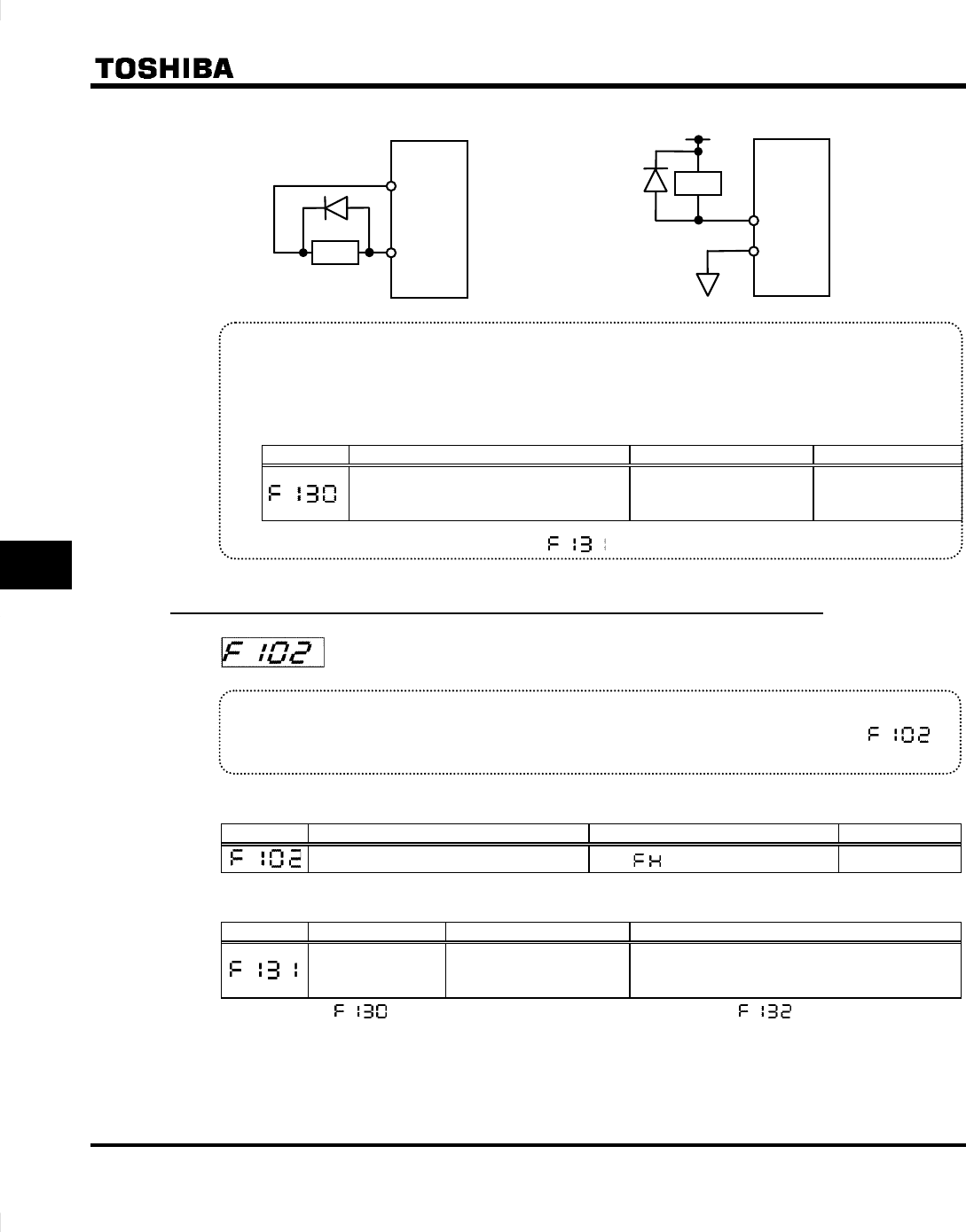
[Connection diagram for sink logic] [Incase of relay]
P24
OUT
Ry
Ry
RC
RY
• Output terminal setting
Output of the low-speed signal (ON signal) between the RY and RC terminals is the factory default set-
ting of the output terminal selection parameter. This setting must be changed to invert the polarity of
the signal.
[Parameter setting]
Title Function Adjustment range Setting
Output terminal selection 1
(RC-RY)
0 ∼ 29
(see section 11)
4 (ON signal)
or
5 (OFF signal)
If the signal output from OUT terminal, set to the value.
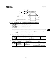
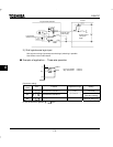
6.1.2 Output of designated frequency reach signal
: Speed reach detection band
• Function
When the output frequency becomes equal to the designated frequency the setting of this
parameter, an ON or OFF signal is generated.
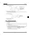
■ Parameter setting of designated frequency and detection band
Title Function Adjustment range Default setting
Speed reach detection band
0.0 ∼ (Hz)
2.5
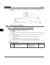
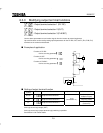
■ Parameter setting of output terminal selection
Title Function Adjustment range Setting
Output terminal
selection 2 (OUT)
0 ∼ 29
(See section 11)
6: RCH (Designated frequency - ON signal),
or
7: RCH (Designated frequency - OFF signal)
Note: Select the parameter to specify RY-RC terminal output, or the parameter to specify
FLA-FLC-FLB terminal output.


