


E6580757
E-7
5
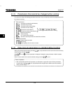
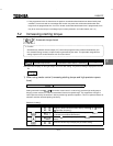
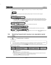
minal, and DOWN (frequency down signal input from external contact) are assigred to the S2 and CLR (fre-
quency up/down clear signal input from external contact) are assigned to the S3 terminals respectively.
Frequencies can be changed by input to the S1 and S2 terminals.
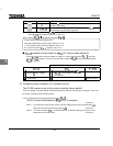
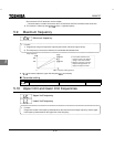
4-20mA current input operation
( )
Used for setting frequencies with 4-20mA current input. Priority is given to current input and FCHG (fre-
quency command forced switching) and ST (standby terminal) are assigned to the S2 and S3 terminals re-
spectively. Remote/manual control (by different frequency commands) can be switched by input to the S2
terminal. The S3 terminal can also be used for coast stop.
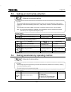
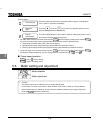
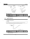
5.5 Selection of operation mode
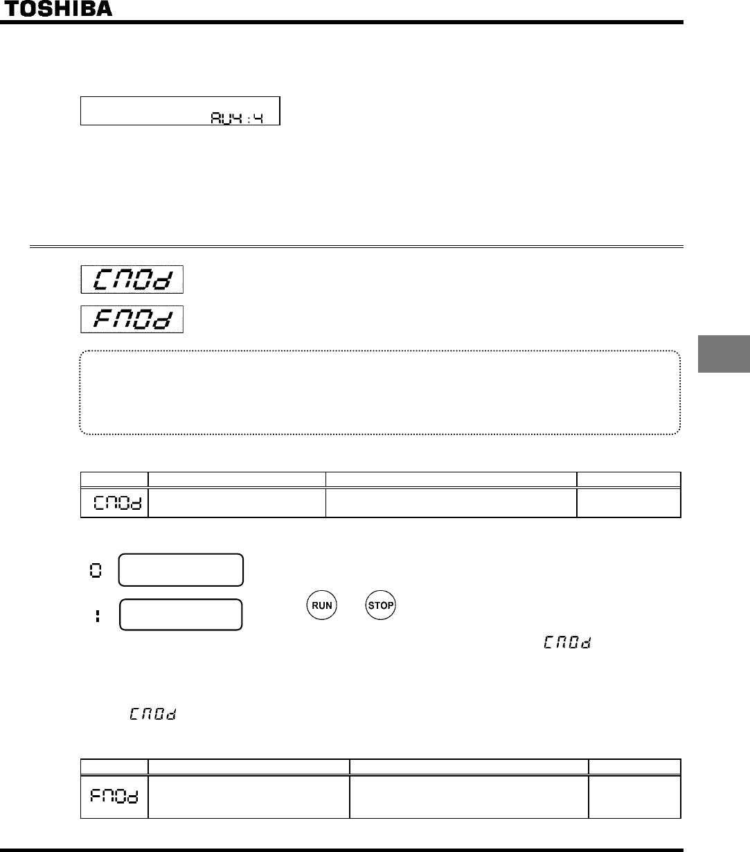
: Command mode selection
: Frequency setting mode selection
• Function
These parameters are to program which command to the inverter (from operation panel or terminal board)
will be given priority in running/stopping the operation and in frequency setting (internal potentiometer, op-
eration panel or terminal board).
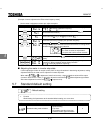
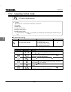
<Command mode selection>
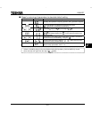
Title Function Adjustment range Default setting
Command mode selection
0: Terminal board
1: Operation panel
1
[Setting value]
:
Terminal board
operation
ON and OFF of an external signal Runs and stops operation.
:
Operation panel
operation
Press the and keys on the operation panel to Run and stop a run.
Performs the Run and stop of a run when the optional expansion panel is used.
* There are two types of function: the function that conforms to commands selected by
, and the func-
tion that conforms only to commands from the terminal board. See the table of input terminal function selection
in Chapter 11.
* When priority is given to commands from a linked computer or terminal board, they have priority over the set-
ting of
.
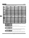
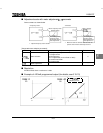
<Frequency setting mode selection>
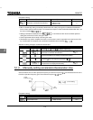
Title Function Adjustment range Default setting
Frequency setting mode selection
0: Terminal board
1: Operation panel
2: Internal potentiometer
2