


E6580757
A-15
1
Remedies:
1.Use the electronic thermal built into the inverter.
The setting of the electronic thermal is done using parameter , ( ).
2.Reduce the inverter's PWM carrier frequency. However, that will increase the motor's magnetic
noise. Use parameter for setting the PWM carrier frequency.
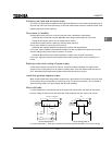
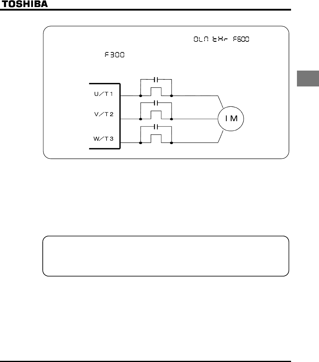
3.This can be improved by installing 0.1µ~0.5µF-1000V film capacitor to the input/output terminals of
each phase in the thermal relay.
Thermal relay
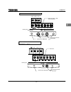
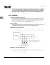
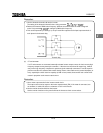
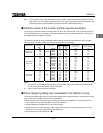
(2) CT and ammeter
If a CT and ammeter are connected externally to detect inverter output current, the leak current's high
frequency component may destroy the ammeter. If the wires are more than 50 meters long, it will be
easy for the high frequency component to pass through the externally connected CT and be superim-
posed on and burn the ammeter with models having motors of low rated current (several A(ampere) or
less), especially the 400V class low capacity (3.7kW or less) models, because the leak current will in-
crease in proportion to the motor's rated current.
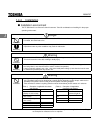
Remedies:
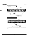
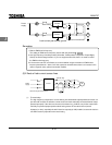
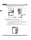
1.Use a meter output terminal in the inverter control circuit.
The output current can be output on the meter output terminal (FM). If the meter is connected, use
an ammeter of 1mAdc full scale or a voltmeter of 7.5V-1mA full scale.
2.Use the monitor functions built into the inverter.
Use the monitor functions on the panel built into the inverter to check current values.