


E6580757
B-8
2
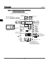
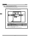
Terminal
symbol
Input/output Function
Electrical
specifications
Inverter internal circuits
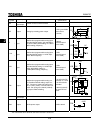
CC
Common to
Input/output
Control circuit's common terminal
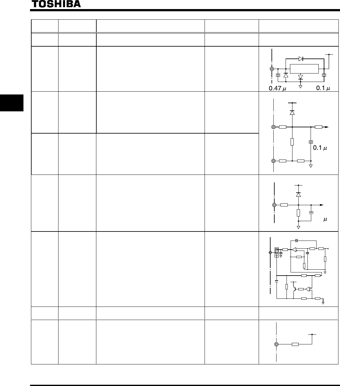
PP Output Analog input setting power output
10Vdc (permissible
load current:
10mAdc)
PP
+24V
I I
*
Input
Multifunction programmable analog input.
Standard default setting: 4(0)~20mAdc in-
put and 0~50Hz (50Hz setting) or 0~60Hz
(60Hz setting) frequency
4-20mA
(internal imped-
ance: 400Ω)
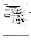
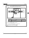
V I A
*
Input
Multifunction programmable analog input.
Standard default setting: 0~10Vdc input
and 0~80Hz frequency
10Vdc
(internal imped-
ance: 30kΩ)
15K
VIA
I I
15K
1K
+5V
150
250
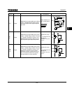
VIB
Input
Multifunction programmable analog input.
Standard default setting: 0~10Vdc input
and 0~50Hz(50Hz setting) or
0~60Hz(60Hz setting) frequency.
10Vdc
(internal imped-
ance: 30kΩ)
15K
+5V
VIB
15K
0.1
FM Output
Multifunction programmable analog out-
put. Standard default setting: output cur-
rent. Connect a 1mAdc full-scale amme-
ter or 7.5Vdc (10Vdc)-1mA full-scale volt-
meter. Can change to 0-20mA (4-20mA)
by jumper JP302 switching.
1mA full-scale DC
ammeter or 7.5Vdc
1mA full-scale dc
voltmeter
0-20mA (4-20mA)
full scale DC am-
meter
FM
FMV
FMC
JP302
4.7K
33K
29K
100K
0.01
0.01
100
100
24V
20K
18K
10K
100K
100K
20K
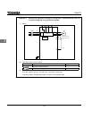
CC
Common to
Input/output
Control circuit's common terminal
P24 Output 24Vdc power output 24Vdc-100mA
PTC
+24V
P24
* The VIA terminal and II terminal cannot be used at the same time.