E6580757
B-7
2
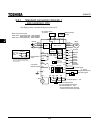
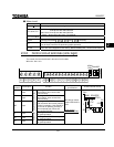
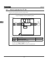
■ Main circuit
Terminal symbol Terminal function
Grounding terminal for connecting inverter case.
R/L1,S/L2,T/L3
200V class: single-phase 200~240V-50/60Hz
three-phase 200~230V-50/60Hz
400V class: three-phase 380~500V-50/60Hz
* Single – phase series don’t have T/L3 terminal.
U/T1,V/T2,W/T3
Connect to a (three-phase induction) motor.
PA,PB
Connect to braking resistors
Change parameters , and if necessary.
PC
This is a negative potential terminal in the internal DC main circuit. DC common power
can be input across the PA terminals (positive potential).
PO,PA
Terminals for connecting a DC reactor (DCL: optional external device). Shorted by a
short bar when shipped from the factory. Before installing DCL, remove the short bar.
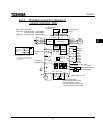
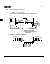
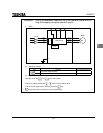
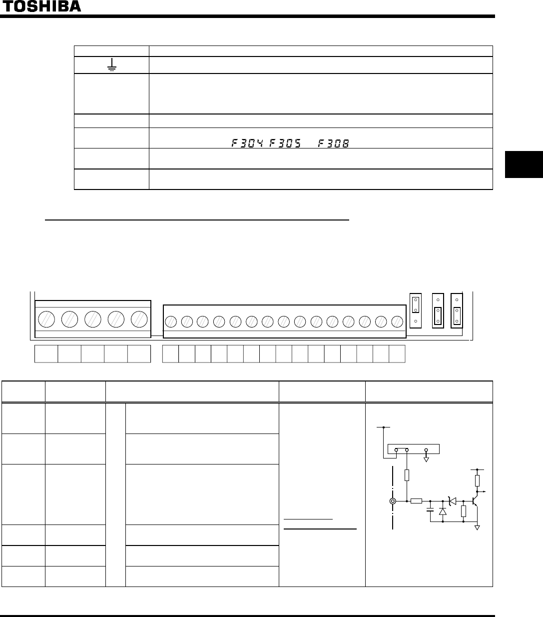
2.3.2 Control circuit terminals (sink logic)
The control circuit terminal board is the same for all models.
Wire size : See 1.3.2.
FLA FLB FLC RY RC CC VIA VIB PP II FM F R RST S1 S2 S3 CC OUTP24
FMC
SINK
FMV
SOURCE
JP302
JP301A
JP301
Terminal
symbol
Input/output Function
Electrical
specifications
Inverter internal circuits
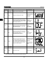
F Input
Shorting across F-CC causes for-
ward rotation; open causes slow-
down and stop.
R Input
Shorting across R-CC causes re-
verse rotation; open causes slow-
down and stop.
RST Input
Shorting across RST-CC causes a
held reset when the inverter protector
function is operating. Note that when
the inverter is operating normally, it
will not operate even if there is a
short across RST-CC.
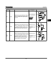
S1 Input
Shorting across S1-CC causes pre-
set speed operation.
S2 Input
Shorting across S2-CC causes pre-
set speed operation.
S3 Input
Multifunction programmablecontact input
Shorting across S3-CC causes pre-
set speed operation.
No voltage contact
input 24Vdc-5mA or
less
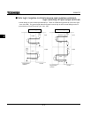
*Sink-source
switchable (JP301)
F
S3
4.7K
JP301
24V
SINK SOURCE
5V
0.1
3.9K
10K
15K


