


E6580757
L-2
12
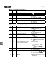
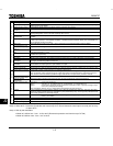
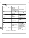
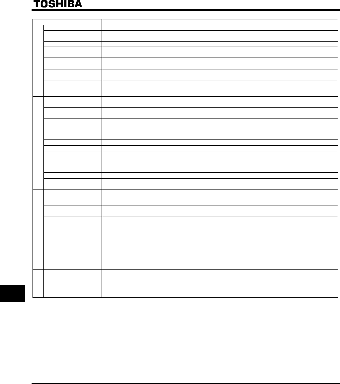
Item Specification
Control system Sinusoidal PWM control
Rated output voltage Adjustable within a range of 100 to 120% of the corrected supply voltage (200/400V) (Unadjustable to any voltage
higher than the input voltage).
Output frequency range 0.5 to 400Hz, default setting: 0.5 to 80Hz, maximum frequency: 30 to 400Hz.
Minimum setting steps of
frequency
0.1Hz: operation panel setting, 0.2Hz: analog input (when the max. frequency is 100Hz).
Frequency accuracy
Digital setting: within ±0.01% of the max. frequency (-10 to +50°C).
Analog setting: within ±0.5% of the max. frequency (25°C ±10°C).
Voltage/frequency
characteristics
V/f constant, variable torque, vector control, automatic torque boost, Base frequency and torque boost amount ad-
justable.
Principal control functions
Frequency setting signal
Front potentiometer and external potentiometer (rated impedance of connectable potentiometer: 1 to 10kΩ), 0 to
10Vdc (input impedance: VIA=30.55kΩ, VB=30kΩ), 4 to 20mAdc (input impedance: 400Ω), The characteristic can
be set arbitrarily by two-point setting.
Start-up fre-
quency/frequency jump
Adjustable within a range of 0 to 10Hz / Up to 3 frequencies can be adjusted together with their widths.
PWM carrier frequency
(Note 1)
Adjustable within a range of 2.0 to 16.5Hz (default: 12kHz).
Acceleration/deceleration
time
0.1 to 3600 seconds, switchable between acceleration/deceleration time 1 and 2, selectable between S-pattern ac-
celeration/deceleration 1 and 2.
Retry operation Restart after a check of the main circuit elements in case the protective function is activated: 10 times (Max.) (ad-
justable with a parameter).
Dynamic braking With a built-in dynamic braking circuit, external braking resistor available (optional).
DC braking Braking start-up frequency: 0 to maximum frequency, braking rate: 0 to 100%, braking time: 0 to 20 seconds.
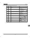
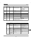
Input terminal functions
(selectable)
Forward/reverse run input signal, jog run input signal, standby signal, preset-speed operation input signal, reset in-
put signal, etc./Switching between sink/source.
Output terminal functions
(selectable)
Frequency lower limit output signal, frequency upper limit output signal, low-speed detection output signal, specified
speed attainment output signal, etc. Open collector, RY output.
Failure detection signal
1c-contact output: 250Vac/2A, cosφ = 0.1, 250Vac/1A, cosφ = 0.4, 3Vdc/1A.
Operation specifications
Output for frequency
meter/output for ammeter
Analog output: (1mAdc full-scale DC ammeter or 7.5Vdc full-scale DC ammeter / Rectifier-type AC voltmeter, 225%
current Max. 1mAdc, 7.5Vdc full-scale), 4 to 20mA/0 to 20mA output.
Protective function Stall prevention, current limitation, over-current, output short circuit, over-voltage, over-voltage limitation, undervolt-
age, ground fault, power supply phase failure, output phase failure overload protection by electronic thermal func-
tion, armature over-load at start-up (5.5kW or larger), load-side over—torque at start, pre-alarm, overheat.
Protection against
momentary power failure
Auto-restart/non-stop control after momentary power failure.
Protective
function
Electronic thermal
characteristic
Switching between standard motor/constant-torque VF motor, overload trip, overload stall selection.
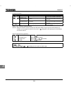
4-digit 7-segments LED Frequency: inverter output frequency.
Alarm: stall alarm “C”, overvoltage alarm “P”, overload alarm “L”, overheat alarm “H”.
Status: inverter status (frequency, cause of activation of protective function, input/output voltage, output
current, etc.) and parameter settings.
Free-unit display: arbitrary unit (e.g. rotating speed) corresponding to output frequency.
Display function
Indicator Lamps indicating the inverter status by lighting, such as RUN lamp, MON lamp, PRG lamp, VEC lamp, ECN lamp,
frequency setting potentiometer lamp, UP/DOWN key lamp and RUN key lamp. The charge lamp indicates that the
main circuit capacitors are electrically charged.
Use environments Indoor, altitude: 1000m (Max.), not exposed to direct sunlight, corrosive gas, explosive gas or vibration (less than
5.9m/s
2
) (10 to 55Hz).
Ambient temperature
-10 to +60°C
Note)1.2.3
Storage temperature
-20 to +65°C
Environments
Relative humidity 20 to 93% (free from condensation and vapor).
Note) 1. Above 40°C : Remove the protective seal from the top of VF-S9.
Note) 2. Above 50°C : Remove the protective seal from the top of VF-S9, and derate the rated output current by 3% for every
°C above 50°C.
Note) 3. Side-by-side installation
• Model of 3.7kW or less : from - 10°C to 40°C (Remove the protective seal from the top of VF-S9).
• Model of 5.5kW or more : from - 10°C to 50°C.