E6580757
E-8
5
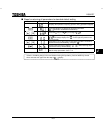
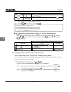
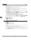
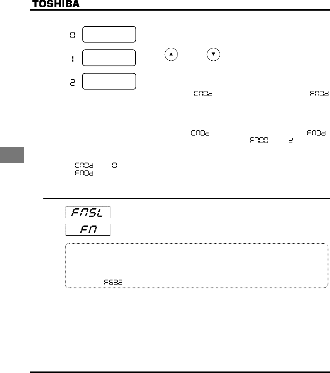
[Setting values]
:
Terminal board
Frequency setting commands are entered by external signals. (VIA/VIB termi-
nals: 0-10Vdc or II terminal: 4-20mAdc)
:
Operation
panel
Press the key or the key on either the operation panel or the ex-
pansion panel (optional) to set frequency.
:
Internal
potentiometer
The internal potentiometer to the inverter is used for setting frequencies. Turning
the notches clockwise raises the frequency.
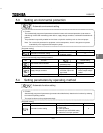
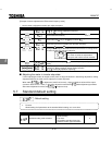
✩ No matter what value the command mode selection
and the frequency setting mode selection
are set to the control input terminal functions described below are always in operative state.
• Reset terminal (default setting: RST, valid only for tripping)
• Standby terminal (when programmed by programmable input terminal functions).
• External input trip stop terminal (when programmed by programmable input terminal functions)
✩ To make changes in the command mode selection
and the frequency setting mode selection ,
first stop the inverter temporarily. (Can be changed while in operation when
is set to .)
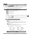
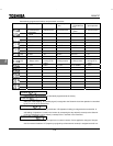
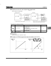
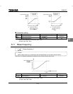
■ Preset-speed operation
: Set to (Terminal board).
: Valid in all setting values.
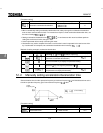
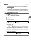
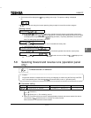
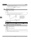
5.6 Meter setting and adjustment
: Meter selection
: Meter adjustment
• Function
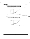
The signal output from the FM terminal is an analog voltage signal.
For the meter, use either a full-scale 0-1mAdc ammeter or full-scale 0-7.5Vdc (or 10Vdc) voltmeter.
Note that the jumper pin JP302 can be set to switch to 0-20mA (4-20mA) current output. Adjust to 4-
20mA with parameter (meter bias).


