


E6580757
A-11
1
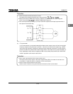
Extremely low loads and low inertia loads
The motor may demonstrate instability such as abnormal vibrations or overcurrent trips at light loads of
50 percent or under of the load percentage, or when the load's inertia moment is extremely small. If that
happens reduce the carrier frequency.
Occurrence of instability
Unstable phenomena may occur under the load and motor combinations shown below.
Combined with a motor that exceeds applicable motor ratings recommended for the inverter
Combined with special motors such as explosion-proof motors
To deal with the above lower the settings of inverter carrier frequency.
(Do not set to 2.2kHz or lower during vector control).
Combined with couplings between load devices and motors with high backlash
In this case, set the S-pattern acceleration/deceleration function and adjust the response time (inertial
moment setting) during vector control or switch to V/f control.
Combined with loads that have sharp fluctuations in rotation such as piston movements
In this case, adjust the response time (inertial moment setting) during vector control or switch to V/f
control.
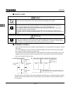
Braking a motor when cutting off power supply
A motor with its power cut off goes into free-run, and does not stop immediately. To stop the motor
quickly as soon as the power is cut off install an auxiliary brake. There are different kinds of brake de-
vices, both electrical and mechanical. Select the brake that is best for the system.
Loads that generate negative torque
When combined with loads that generate negative torque the protection for overvoltage and overcurrent
on the inverter will go into operation and may cause a trip. For this kind of situation, you must install a
dynamic braking resistor, etc. that complies with the load conditions.
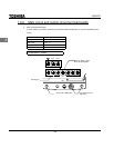
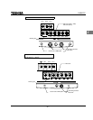
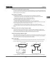
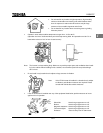
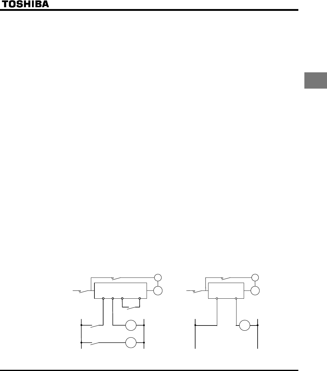
Motor with brake
If a motor with brake is connected directly to the output side of the inverter, the brake will not release
because voltage at startup is low. Wire the brake circuit separately from the motor's main circuits.
Three-phase
power supply
Three-phase
power supply
MC1
MC2
B
RY RC
MC3
MC2
MC1
MC2 (Non-exciting brake)
B
IM
MC3
MC1
MC3
FLB FLC ST CC
MC2
IM
Circuit Configuration 1
Circuit Configuration 2
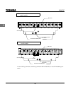
In circuit configuration 1, the brake is turned on and off through MC2 and MC3. If the circuit is config-