


E6580757
M-2
13
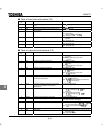
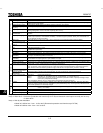
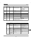
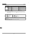
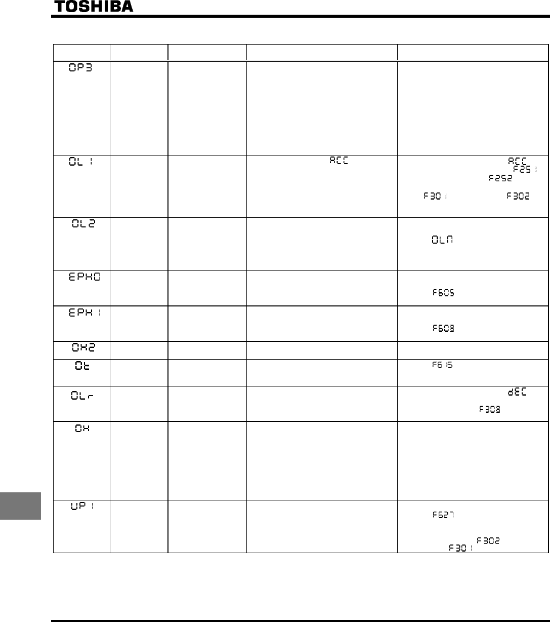
(Continued)
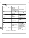
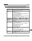
Error code
Communication
No.
Problem Possible causes Remedies
C Overvoltage during
constant-speed op-
eration
• The input voltage fluctuates abnormally.
(1) The power supply has a capacity of
200kVA or more.
(2) A power factor improvement capacitor is
opened or closed.
(3) A system using a thyristor is connected
to the same power distribution line.
• The motor is in a regenerative state be-
cause the load causes the motor to run at
a frequency higher than the inverter out-
put frequency.
• Insert a suitable input reactor.
• Install a dynamic braking resistor.
D Inverter overload
• The acceleration time is too short.
• The DC braking amount is too large.
• The V/F setting is improper.
• A restart signal is input to the rotating
motor after a momentary stop, etc.
• The load is too large.
• Increase the acceleration time .
• Reduce the DC braking amount
and the DC braking time .
• Check the V/F parameter setting.
• Use (auto-restart) and
(ride-through control).
• Use an inverter with a larger rating.
E Motor overload
• The V/F setting is improper.
• The motor is locked up.
• Low-speed operation is performed con-
tinuously.
• An excessive load is applied to the motor
during operation.
• Check the V/F parameter setting.
• Check the load (operated machine).
• Adjust to the overload that the
motor can withstand during operation in a
low speed range.
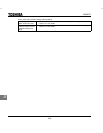
* 9 Output phase failure
• A phase failure occurred in the output line
of the main circuit.
• Check the main circuit output line, motor,
etc., for phase failure.
• Enable (Output phase failure de-
tection).
* 8 Input phase failure
• A phase failure occurred in the input line
of the main circuit.
• Check the main circuit input line for phase
failure.
• Enable (input phase failure detec-
tion).
2Eh External thermal trip
• A thermal trip command is entered from
an external input device.
• Check the external input device.
* 20h Over-torque trip
• The load torque rises up to the over-
torque detection level during operation
• Enable (Over - torque trip selection)
• Check whether the system is in a normal
condition.
F Dynamic braking re-
sistor overload trip
• The deceleration time is too short.
• The dynamic braking amount is too large.
• Increase the deceleration time .
• Use a dynamic resistor with a larger ca-
pacity (W) and adjust (PBR ca-
pacity parameter) accordingly.
10h Overheat
• The cooling fan does not rotate.
• The ambient temperature is too high.
• The vent is blocked up.
• A heat generating device is installed close
to the inverter.
• The thermistor in the unit is broken.
• Restart the operation by resetting the
inverter after it has cooled down enough.
• The fan requires replacement if it does
not rotate during operation.
• Secure sufficient space around the
inverter.
• Do not place any heat-generating device
near the inverter.
• Make a service call.
* 1E Undervoltage trip
(main circuit)
• The input voltage (in the main circuit) is
too low.
• Check the input voltage.
• Enable (undervoltage trip selec-
tion).
• To cope with a momentary stop due to
undervoltage, enable (ride-through
control) and (auto-restart).
* With a parameter, you can choose between trip-on and -off.
(Continued overleaf)