


100 CHAPTER 6: VLAN OPERATION
Configuration Procedure
1 Create VLAN 2 and enter its view.
[SW5500]vlan 2
2 Add Ethernet1/0/1 and Ethernet1/0/2 to VLAN2.
[SW5500-vlan2]port ethernet1/0/1 to ethernet1/0/2
3 Create VLAN 3 and enter its view.
[SW5500-vlan2]vlan 3
4 Add Ethernet1/0/3 and Ethernet1/0/4 to VLAN3.
[SW5500-vlan3]port ethernet1/0/3 to ethernet1/0/4
VLAN Configuration
Example Two
Networking Requirements
Configure an IP address on a VLAN interface.
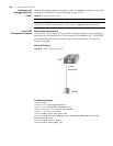
Networking Diagram
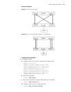
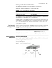
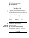
Figure 24 shows an example of a typical VLAN configuration.
Figure 24 VLAN Configuration Example 2
Configuration Procedure
1 If the VLAN does not currently exist, then create it. This example uses VLAN ID 3.
[SW5500]vlan 3
[SW5500-vlan3
]quit
2 Enter the VLAN interface view:
[SW5500]interface vlan-interface 3
3 Provide the IP address and subnet mask:
[SW5500-Vlan-interface3]ip address 192.168.1.5 255.255.255
[SW5500-Vlan-interface3]quit
Protocol-Based VLAN
Configuration
Comparing with port-based VLANs, protocol-based VLANs operate in a different way.
After you configure protocol-based VLANs for a switch, the switch inserts tags
automatically in the received untagged packets according to the protocols with which
the packets are encapsulated. This enables packets of specific protocols to be
transmitted in corresponding VLANs. For ease of network management and
maintenance, you can associate services with specific VLANs by configuring
protocol-based VLANs.
Configuring
Protocol-Based VLANs
The following section describes protocol-based VLAN configuration tasks:
■ Creating a VLAN protocol type
■ Associating a port with a protocol-based VLAN