


556 CHAPTER 26: RSTP CONFIGURATION
For detailed information about the configuration commands, refer to the Command
Manual.
Display and Debug RSTP After the above configuration, execute display command in all views to display the
running of the RSTP configuration, and to verify the effect of the configuration.
Execute
reset command in User View to clear the statistics of RSTP module. Execute
debugging command in User View to debug the RSTP module.
Table 614 Display and Debug RSTP
RSTP Configuration
Example
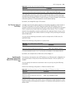
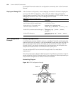
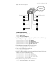
Networking Requirements
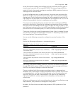
In the following scenario, Switch C serves as a standby of Switch B and forwards data
when a fault occurs on Switch B. They are connected to each other with two links, so
that, in case one of the links fails, the other one can still work normally. Switch D
through Switch F are directly connected with the downstream user computers and
they are connected to Switch C and Switch B with uplink ports.
You can configure RSTP on the Switch B through Switch F to meet these
requirements.
Only the configurations related to RSTP are listed in the following procedure. Switch A
serves as the root. Switch D through Switch F are configured in same way basically, so
only the RSTP configuration on Switch D will be introduced.
Networking Diagram
Figure 163 RSTP Configuration Example
Operation Command
Display RSTP configuration information about
the local Switch and the specified ports
display stp [ interface
interface_list ]
Display the list of STP-Ignored VLANs display stp ignored-vlan
Clear RSTP statistics information reset stp [ interface interface_list
]
Enable RSTP (error/event/packet) debugging debugging stp { error | event |
packet }
Disable RSTP debugging undo debugging stp { error | event |
packet }
Switch B
Switch C
Switch A
Switch D
E1/0/1
E1/0/2
E1/0/3
E1/0/1
E1/0/2
E1/0/3
E1/1 E1/2 E1/1
E1/2
E1/2
E1/1
E1/0/24
E1/0/23 E1/0/23
E1/0/24
Switch E Switch F
GE2/0/1 GE2/0/2