


532 CHAPTER 25: AUTO DETECT CONFIGURATION
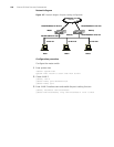
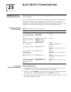
Network diagram
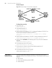
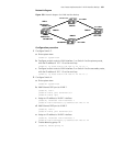
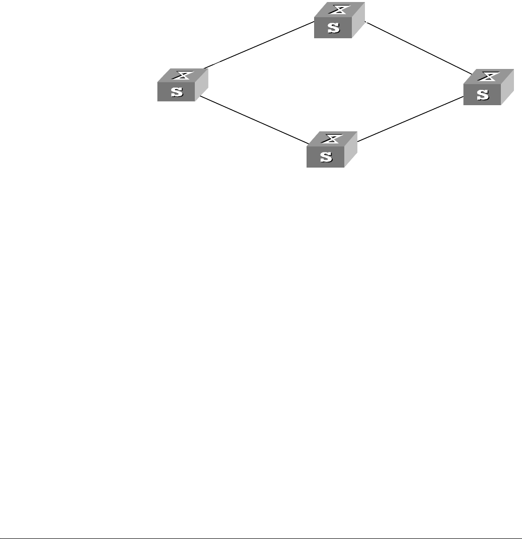
Figure 155 Network diagram for auto detect configuration
Configuration procedure
1 Enter system view.
<S5500> system-view
2 Create detecting group 10.
[S5500] detect-group 10
3 Specify to detect the IP address of 10.1.1.4, taking the IP address of 192.168.1.2 as
the next hop and setting the detecting number to 1.
[S5500-detect-group-10] detect-list 1 ip address 10.1.1.4 nexthop
192.168.1.2
4 Specify to detect the IP address of 192.168.2.2, setting the detecting number to 2.
[S5500-detect-group-10] detect-list 2 ip address 192.168.2.2
5 Specify to return reachable as the detecting result if one of the two IP addresses is
reachable.
[S5500-detect-group-10] option or
6 Set the detecting interval to 60 seconds.
[S5500-detect-group-10] timer loop 60
7 Set the maximum number of retries during a detecting operation to 3.
[S5500-detect-group-10] retry 3
8 Set the detecting timeout time to 3 seconds.
[S5500-detect-group-10] timer wait 3
[S5500-detect-group-10] quit
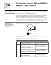
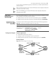
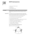
Auto Detect
Implementation
The results of auto detect operations (reachable or unreachable) can be used to
determine whether or not to enable some functions. The auto detect function can be
utilized in:
■ Static routing
■ Virtual router redundancy protocol (VRRP)
■ Interface backup
192.168.1.1
192.168.2.1
192.168.1.2
192.168.2.2 20.1.1.2
10.1.1.3
Ethernet 1/0/1
10.1.1.4
Ethernet 2/0/1
Switch A
Switch B
Switch C
Switch D
192.168.1.1/24
192.168.2.1/24
192.168.1.2/24
192.168.2.2/24 20.1.1.2/24
10.1.1.3/24
Ethernet 1/0/1
10.1.1.4/24
Ethernet 2/0/1
Switch A
Switch B
Switch C
Switch D
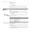
VLAN 1
VLAN 2
192.168.1.1
192.168.2.1
192.168.1.2
192.168.2.2 20.1.1.2
10.1.1.3
Ethernet 1/0/1
10.1.1.4
Ethernet 2/0/1
Switch A
Switch B
Switch C
Switch D
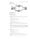
192.168.1.1/24
192.168.2.1/24
192.168.1.2/24
192.168.2.2/24 20.1.1.2/24
10.1.1.3/24
Ethernet 1/0/1
10.1.1.4/24
Ethernet 2/0/1
Switch A
Switch B
Switch C
Switch D
VLAN 1
VLAN 2