


298 CHAPTER 17: NETWORK PROTOCOL OPERATION
Configuration Procedure
1 Create a DHCP server group that will use two DHCP servers (a master and an optional
backup) and assign it the IP addresses of the two DHCP servers (the first IP address is
the master).
[SW5500]dhcp-server 0 ip 192.168.1.1 192.168.2.1
2 Configure the Switch so all clients use DHCP server group '0'.
[SW5500]interface vlan-interface 1
[SW5500-Vlan-interface1]dhcp-server 0
[SW5500-Vlan-interface1]quit
[SW5500]interface vlan-interface 10
[SW5500-Vlan-interface10]dhcp-server 0
[SW5500-Vlan-interface10]quit
DHCP Relay
Configuration Example
Two
Networking Requirements
The segment address for the DHCP Client is 10.110.0.0, which is connected to a port
in VLAN2 on the Switch. The IP address of the DHCP Server is 202.38.1.2. The DHCP
packets should be forwarded using the Switch with DHCP Relay enabled. A DHCP
Client can get its IP address and other configuration information from the DHCP
Server.
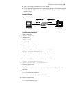
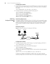
Networking Diagram
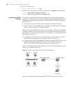
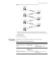
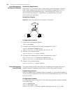
Figure 75 Networking Diagram of Configuration DHCP Relay
Configuration Procedure
1 Configure the group number of DHCP Server as 1 and the IP address as 202.38.1.2.
[SW5500]dhcp-server 1 ip 202.38.1.2
2 Associate the VLAN interface 2 with DHCP Server group 1.
[SW5500]interface vlan 2
[SW5500-Vlan-interface2]dhcp-server 1
3 Configure the IP address of the VLAN interface 2, which must be in the same segment
as DCHP Client.
[SW5500-Vlan-interface2]ip address 10.110.1.1 255.255.0.0
To allocate an IP address successfully for the DHCP Client, you need to make the
necessary configuration on the DHCP Server, which varies, depending on device type.
Ethernet
Ethernet
Internet
DHCP client
DHCP client
Switch ( DHCP Relay )
10.110.0.0
DHCP Server
202.38.1.2
10.110.1.1
202.38.0.0
202.38.1.1