


256 CHAPTER 16: IP ROUTING PROTOCOL OPERATION
Only when the current DR is offline does the DR change. Shut down Switch A, and
run
display ospf peer command on Switch D to display its neighbors. Note that
the original BDR (Switch C) becomes the DR, and Switch B is the new BDR.
If all Ethernet Switches on the network are removed and added again, Switch B is
elected as the DR (with a priority of 200), and Switch A becomes the BDR (with a
priority of 100). Switching off and restarting all the switches initiates a new round of
DR and BDR selection.
Example: Configuring
OSPF Virtual Link
Networking requirements
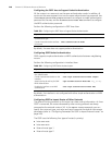
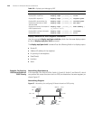
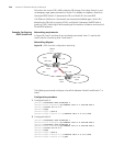
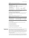
In Figure 58, Area 2 and Area 0 are not directly connected. Area 1 is used as the
transit area for connecting Area 2 and Area 0.
Networking diagram
Figure 58 OSPF virtual link configuration networking
The following commands configure a virtual link between Switch B and Switch C in
Area 1.
Configuration procedure
1 Configure Switch A:
[Switch A]interface Vlan-interface 1
[Switch A-Vlan-interface1]ip address 196.1.1.1 255.255.255.0
[Switch A]router id 1.1.1.1
[Switch A]ospf
[Switch A-ospf-1]area 0
[Switch A-ospf-1-area-0.0.0.0]network 196.1.1.0 0.0.0.255
2 Configure Switch B:
[Switch B]interface vlan-interface 7
[Switch B-Vlan-interface7]ip address 196.1.1.2 255.255.255.0
[Switch B]interface vlan-interface 8
[Switch B-Vlan-interface8]ip address 197.1.1.2 255.255.255.0
[Switch B]router id 2.2.2.2
[Switch B]ospf
[Switch B-ospf-1]area 0
[Switch B-ospf-1-area-0.0.0.0]network 196.1.1.0 0.0.0.255
[Switch B-ospf-1-area-0.0.0.0]quit
152.1.1.1/24
196.1.1.2/24
Switch A
1.1.1.1
Switch B
2.2.2.2
Virtual
Link
197.1.1.2/24
Area 2
Area 1
Area 0
Switch C
3.3.3.3
197.1.1.1/24
196.1.1.1/24