


Displaying and Clearing VRRP Information 157
Displaying and
Clearing VRRP
Information
You can execute the display command in any view to view VRRP configuration.
VRRP Configuration
Example
This section contains examples of VRRP configurations.
Single-VRRP Backup
Group Configuration
Example
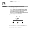
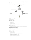
Network requirements
Host A uses the VRRP virtual router comprising switch A and switch B as its default
gateway to visit host B on the Internet.
The information about the VRRP backup group is as follows:
■ VRRP backup group ID: 1
■ Virtual router IP address: 202.38.160.111
■ Master switch: Switch A
■ Backup switch: Switch B
■ Preemptive mode: enabled
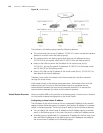
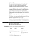
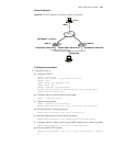
Network diagram
Figure 39 Network diagram for single-VRRP backup group configuration
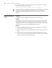
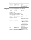
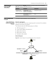
Table 139 Display and Clear VRRP Information
Operation Command Description
Display VRRP state
information and
statistics information
display vrrp [ interface
vlan-interface vlan-id |
statistics [ vlan-interface
vlan-id ] ] [ virtual-router-ID ]
You can execute the display vrrp
command in any view
Clear VRRP statistics reset vrrp statistics [
vlan-interface vlan-id ] [
virtual-router-ID ]
Execute the reset command in user
view
Virtual IP address: 202.38.160.111
Switch_A
Host A
202.38.160.3
-
Vlan-interface2: 202.38.160.1
Internet
Switch_B
-
Vlan-interface2: 202.38.160.2
-
Vlan-interface3: 10.100.10.2
Host B
10.2.3.1
Virtual IP address: 202.38.160.111
Switch_A
Host A
202.38.160.3
-
Vlan-interface2: 202.38.160.1
Internet
Switch_B
-
Vlan-interface2: 202.38.160.2
-
Vlan-interface3: 10.100.10.2
Host B
10.2.3.1