


Typical NTP Configuration Examples 501
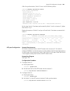
After the synchronization, Switch 2 turns into the following status:
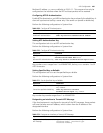
[switch2]display ntp-service status
clock status: synchronized
clock stratum: 8
reference clock ID: 1.0.1.11
nominal frequency: 100.0000 Hz
actual frequency: 100.0000 Hz
clock precision: 2^17
clock offset: 0.0000 ms
root delay: 0.00 ms
root dispersion: 10.94 ms
peer dispersion: 10.00 ms
reference time: 20:54:25.156 UTC Mar 7 2002(C0325201.2811A112)
By this time, Switch 2 has been synchronized by Switch 1 and is at stratum 3, higher
than Switch 1 by 1.
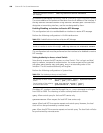
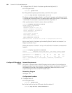
Display the sessions of Switch 2 and you will see Switch 2 has been connected with
Switch 1.
[switch2]display ntp-service sessions
source reference stra reach poll now offset delay disper
********************************************************************
[12345]127.127.1.0 LOCAL(0) 7 377 64 57 0.0 0.0 1.0
[5]1.0.1.11 0.0.0.016 0 64 - 0.0 0.0 0.0
[5]128.108.22.44 0.0.0.0 16 0 64 - 0.0 0.0 0.0
note: 1 source(master),2 source(peer),3 selected,4 candidate,5
configured
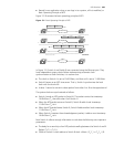
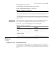
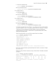
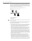
NTP peer Configuration Network Requirements
On Switch 3, set local clock as the NTP master clock at stratum 2. On Switch 2,
configure SW5500 1 as the time server in server mode and set the local equipment as
in client mode. At the same time, Switch 5 sets Switch 4 as its peer. (Note that Switch
3 must support setting local clock as the NTP master clock.)
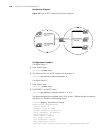
Networking Diagram
See Figure 132.
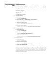
Configuration Procedure
1 Configure Switch 3:
a Enter System View.
<switch3> system-view
b Set the local clock as the NTP master clock at stratum 2.
[switch3]ntp-service refclock-master 2
2 Configure Switch 4:
a Enter System View.
<switch4> system-view
b Set Switch 1 as the NTP server at stratum 3 after synchronization.
[switch4]ntp-service unicast-server 3.0.1.31