


524 CHAPTER 23: PORT TRACKING CONFIGURATION
Network diagram
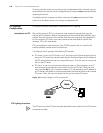
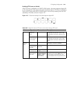
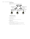
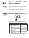
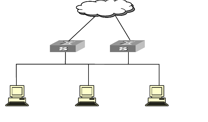
Figure 147 Network diagram for port tracking configuration
Configuration procedure
Configure the master switch.
1 Enter system view.
<S5500> system-view
System View: return to User View with Ctrl+Z.
2 Create VLAN 2.
[S5500] vlan 2
[S5500-vlan2] port Ethernet1/0/1
[S5500-vlan2] quit
3 Enter VLAN 2 interface view and enable the port tracking function.
[S5500] interface vlan-interface2
[S5500-Vlan-interface2] vrrp vlan-Interface 2 vrid 1 track
Ethernet
Mas ter
Host 1 Host 2 Host 3
10.100.10.7 10.100.10.8 10.100.10.9
Virtual IP address10.100.10.1
Network
Backup
Virtual IP address10.100.10.1
Actual IP address10.100.10.2 Actual IP address10.100.10.3
Netw ork
Ethernet
Mas ter
Host 1 Host 2 Host 3
10.100.10.7 10.100.10.8 10.100.10.9
Virtual IP address10.100.10.1
Network
Backup
Virtual IP address10.100.10.1
Actual IP address10.100.10.2 Actual IP address10.100.10.3
Netw ork