


160 CHAPTER 12: VRRP CONFIGURATION
2 Configure switch B.
a Configure VLAN 2.
<LSW-B> system-view
System View: return to User View with Ctrl+Z.
[LSW-B] vlan 2
[LSW-B-vlan2] port Ethernet 1/0/5
[LSW-B-vlan2] quit
[LSW-B] interface vlan-interface 2
[LSW-B-Vlan-interface2] ip address 202.38.160.2 255.255.255.0
[LSW-B-Vlan-interface2] quit
b Configure that the virtual router can be pinged.
[LSW-B] vrrp ping-enable
c Create a backup group.
[LSW-B] interface vlan-interface 2
[LSW-B-Vlan-interface2] vrrp vrid 1 virtual-ip 202.38.160.111
d Set the authentication key for the backup group.
[LSW-B-Vlan-interface2] vrrp authentication-mode md5 switch
e Set the master to send VRRP packets once in every 5 seconds.
[LSW-B-Vlan-interface2] vrrp vrid 1 timer advertise 5
Normally, Switch A functions as the gateway, but when VLAN 3 interface on Switch A
goes down, its priority will be reduced by 30, lower than that of Switch B so that
Switch B will preempt the master for gateway services instead.
When VLAN 3 interface recovers, switch A will resume its gateway function as the
master.
Multiple-VRRP Backup
Group Configuration
Example
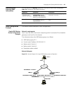
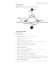
Network requirements
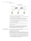
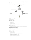
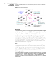
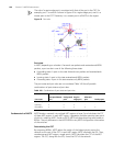
A switch can function as backup switches of multiple backup groups.
Multiple-backup group configuration can implement load balancing. For example,
Switch A operates as the master switch of backup group 1 and a backup switch in
backup group 2. Similarly, Switch B operates as the master switch of backup group 2
and a backup switch in backup group 1. Some hosts in the network take virtual router
1 as the gateway, while others take virtual router 2 as the gateway. In this way, both
load balancing and mutual backup are implemented.