


504 CHAPTER 22: FILE SYSTEM MANAGEMENT
Configure NTP Multicast
Mode
Network Requirements
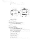
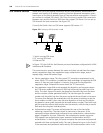
Switch 3 sets the local clock as the master clock at stratum 2 and multicast packets
from Vlan-interface2. Set Switch 4 and Switch 1 to receive multicast messages from
their respective Vlan-interface2. (Note that Switch 3 must support setting local clock
as the NTP master clock.)
Networking Diagram
See Figure 132.
Configuration Procedure
1 Configure Switch 3:
a Enter System View.
<switch3> system-view
b Set the local clock as the NTP master clock at stratum 2.
[switch3]ntp-service refclock-master 2
c Enter Vlan-interface2 view.
[switch3]interface vlan-interface 2
d Set it as a multicast server.
[switch3-Vlan-Interface2]ntp-service multicast-server
2 Configure Switch 4:
a Enter System View.
<switch4> system-view
b Enter Vlan-interface2 view.
[switch4]interface vlan-interface 2
c Enable multicast client mode.
[switch4-Vlan-Interface2]ntp-service multicast-client
3 Configure Switch 1:
a Enter System View.
<switch1> system-view
b Enter Vlan-interface2 view.
[switch1]interface vlan-interface 2
c Enable multicast client mode.
[switch1-Vlan-Interface2]ntp-service multicast-client
The above examples configure Switch 4 and Switch 1 to receive multicast messages
from Vlan-interface2, Switch 3 multicast messages from Vlan-interface2. Since Switch
1 and Switch 3 are not located on the same segments, Switch 1 cannot receive the
multicast packets from Switch 3, while Switch 4 is synchronized by Switch 3 after
receiving the multicast packet.