


VRRP Configuration Example 161
Network diagram
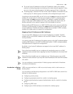
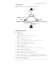
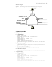
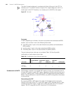
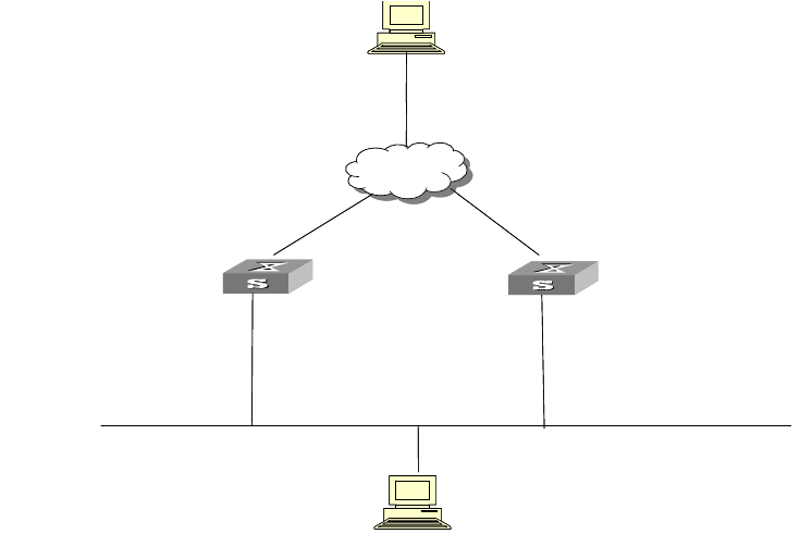
Figure 41 Network diagram for multiple-VRRP backup group configuration
Configuration procedure
1 Configure Switch A.
a Configure VLAN 2.
<LSW-A> system-view
System View: return to User View with Ctrl+Z.
[LSW-A] vlan 2
[LSW-A-vlan2] port Ethernet 1/0/6
[LSW-A-vlan2] quit
[LSW-A] interface vlan-interface 2
[LSW-A-Vlan-interface2] ip address 202.38.160.1 255.255.255.0
b Create backup group 1.
[LSW-A-Vlan-interface2] vrrp vrid 1 virtual-ip 202.38.160.111
c Set the priority for backup group 1.
[LSW-A-Vlan-interface2] vrrp vrid 1 priority 150
d Create backup group 2.
[LSW-A-Vlan-interface2] vrrp vrid 2 virtual-ip 202.38.160.112
2 Configure Switch B.
a Configure VLAN 2.
<LSW-B> system-view
System View: return to User View with Ctrl+Z.
[LSW-B] vlan 2
[LSW-B-vlan2] port Ethernet 1/0/6
[LSW-B-vlan2] quit
[LSW-B] interface vlan-interface 2
[LSW-B-Vlan-interface2] ip address 202.38.160.2 255.255.255.0
Backup goup 1:
Virtual IP address: 202.38.160.111
Switch_A
Host A
202.38.160.3
-
Vlan-interface2: 202.38.160.1
Internet
Switch_B
-
Vlan-interface2: 202.38.160.2
-
Vlan-interface3: 10.100.10.2
Host B
10.2.3.1
Backup goup 2:
Virtual IP address: 202.38.160.112
Backup goup 1:
Virtual IP address: 202.38.160.111
Switch_A
Host A
202.38.160.3
-
Vlan-interface2: 202.38.160.1
Internet
Switch_B
-
Vlan-interface2: 202.38.160.2
-
Vlan-interface3: 10.100.10.2
Host B
10.2.3.1
Backup goup 2:
Virtual IP address: 202.38.160.112