


546 CHAPTER 26: RSTP CONFIGURATION
Configure the
timeout time
factor of a
Switch
The Switch, if has not
received any Hello
packet from the
upstream Switch for
thrice the Hello Time,
will consider the
upstream Switch
failed and recalculate
the spanning tree.
In a stable network, it is recommended to
set the timeout time factor to 5, 6, or 7.
Then the Switch will not consider the
upstream Switch failed unless it has not
received any Hello packet from it for 5, 6,
or 7 times the Hello Time.
Specify the
maximum
transmission
rate of STP
packets on a
port
No Ethernet port can
send more than 3 STP
packets within one
Hello Time.
The more STP packets a port sends within
one Hello Time, the more resources are
consumed. It is therefore recommended to
limit the transmission rate of STP packets
on a port, preferably to the default value.
Specify the
preference of a
port
All Ethernet ports are
at the preference
128.
The port preference plays an important role
in root port selection. You can make a port
to be root port by giving it a smallest
preference value.
Configure
whether to
connect a port
with a
peer-to-peer link
RSTP can detect
automatically
whether the current
Ethernet port is
connect to a
peer-to-peer link.
The two ports connected with a
peer-to-peer link can rapidly transit to the
forwarding status by sending synchronous
packets, eliminating unnecessary
forwarding delay.
Specify the Path
Cost on a port
Specify the
standard to
follow in Path
Cost calculation
The Switch gets the
path cost of a port
from the link rate
under the IEEE 802.1t
standard.
The path cost of a port is closely related to
the transmission rate of the link the port
connected with. The larger the link rate is,
the smaller the path cost shall be. It is
recommended to use the default
configuration.
Specify mCheck
for a port
- You can change the operational mode of a
port from STP-compatible to RSTP.
Configure the
protection
functions on a
Switch
No protection
function is enabled
on a Switch.
It is recommended to enable the loop
protection function on the intermediate
Switches.
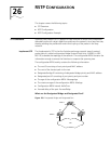
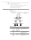
Switch E,
Switch F
and
Switch G
Enable the STP
feature on the
Switch
Enable the STP
feature on the
port
The STP feature is
disabled from the
Switch, but will be
enabled on all ports
once being enabled
on the Switch.
The configuration of STP feature status on
the port will not take effect if the STP
feature is disabled from the Switch.
Configure RSTP
operational
mode
The Switch works in
RSTP mode.
If there are Switches respectively running
STP and RSTP on the network, it is
recommended to set the Switch in
STP-compatible mode.
Configure the
timeout time
factor of a
Switch
The Switch, if has not
received any Hello
packet from the
upstream Switch for
thrice the Hello Time,
will consider the
upstream Switch
failed and recalculate
the spanning tree.
In a stable network, it is recommended to
set the timeout time factor to 5, 6, or 7.
Then the Switch will not consider the
upstream Switch failed unless it has not
received any Hello packet from it for 5, 6,
or 7 times the Hello Time.
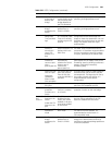
Table 595 RSTP Configuration (continued)
Device Configuration Default Value Note