


542 CHAPTER 26: RSTP CONFIGURATION
Switch B compares the configuration BPDUs of the ports and selects the BP1 BPDU
as the optimum one. Thus BP1 is elected as the root port and the configuration
BPDUs of Switch B ports are updated as follows.
The configuration BPDU of the root port BP1 retains as {0, 0, 0, BP1}. BP2 updates
root ID with that in the optimum configuration BPDU, the path cost to root with 5,
sets the designated bridge as the local Switch ID and the designated port ID as the
local port ID. Thus the configuration BPDU becomes {0, 5, 1, BP2}.
Then all the designated ports of Switch B transmit the configuration BPDUs
regularly.
■ Switch C:
CP2 receives from the BP2 of Switch B the configuration BPDU {1, 0, 1, BP2} that
has not been updated and then the updating process is launched. {1, 0, 1, BP2}.
CP1 receives the configuration BPDU {0, 0, 0, AP2} from Switch A and Switch C
launches the updating. The configuration BPDU is updated as {0, 0, 0, AP2}.
By comparison, CP1 configuration BPDU is elected as the optimum one. The CP1 is
thus specified as the root port with no modifications made on its configuration
BPDU. However, CP2 will be blocked and its BPDU also remains the same, but it
will not receive the data (excluding the STP packet) forwarded from Switch B until
spanning tree calculation is launched again by some new events. For example, the
link from Switch B to C is down or the port receives a better configuration BPDU.
CP2 will receive the updated configuration BPDU, {0, 5, 1, BP2}, from Switch B.
Since this configuration BPDU is better then the old one, the old BPDU will be
updated to {0, 5, 1, BP2}.
Meanwhile, CP1 receives the configuration BPDU from Switch A but its
configuration BPDU will not be updated and retain {0, 0, 0, AP2}.
By comparison, {0, 5, 1, BP2}, the configuration BPDU of CP2, is elected as the
optimum one, CP2 is elected as the root port, whose BPDU will not change, while
CP1 will be blocked and retain its BPDU, but it will not receive the data forwarded
from Switch A until spanning tree calculation is triggered again by some changes.
For example, the link from Switch B to C as down.
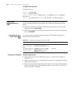
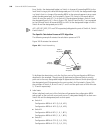
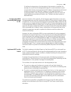
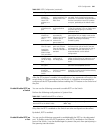
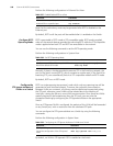
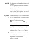
Thus the spanning tree is stabilized. The tree with the root bridge A is illustrated in
Figure 161.
Figure 161 The Final Stabilized Spanning Tree
Switch A
with priority 0
Switch C
with priority 2
Switch B
with priority 1
CP2
BP2
BP1
AP1
4
5