


264 CHAPTER 16: IP ROUTING PROTOCOL OPERATION
stop forwarding the packet to the network. Using the following configuration tasks,
you can choose to forward the broadcast packet to the network for broadcast.
Perform the following configuration in system view.
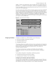
Displaying and
Debugging the Routing
Policy
Enter the
display command in any view to display the operation of the routing policy
configuration, and to verify the effect of the configuration.
Typical IP Routing Policy
Configuration Example
Configuring the Filtering of the Received Routing Information
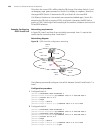
Networking Requirements
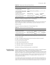
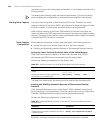
■ Switch A communicates with Switch B, running OSPF protocol.
■ Import three static routes by enabling the OSPF protocol on Switch A.
■ The route filtering rules can be configured on Switch B to make the received three
static routes partially visible and partially shielded. This means that routes in the
network segments 20.0.0.0 and 40.0.0.0 are visible while those in the network
segment 30.0.0.0 are shielded.
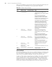
Networking diagram
Figure 60 Filtering the received routing information
Configuration procedure
1 Configure Switch A:
a Configure the IP address of VLAN interface.
[Switch A]interface vlan-interface 100
[Switch A-Vlan-interface100]ip address 10.0.0.1 255.0.0.0
[Switch A]interface vlan-interface 200
[Switch A-Vlan-interface200]ip address 12.0.0.1 255.0.0.0
b Configure three static routes.
[Switch A]ip route-static 20.0.0.1 255.0.0.0 12.0.0.2
[Switch A]ip route-static 30.0.0.1 255.0.0.0 12.0.0.2
[Switch A]ip route-static 40.0.0.1 255.0.0.0 12.0.0.2
Table 260 Configuring to forward layer 3 broadcast packets
Operation Command Description
Enter system view system-view —
Configure to forward
layer 3 broadcast packets
ip forward-broadcast Required
By default, the switch does not forward
layer 3 broadcast packets
Table 261 Displaying and Debugging the Routing Policy
Operation Command
Display the routing policy display route-policy [ route_policy_name ]
Display the address prefix list
information
display ip ip-prefix [ ip_prefix_name ]
area 0
stati c 20.0.0.0/8
30.0.0.0/8
40.0.0.0/8
R o u terID:1.1.1.1
10.0.0.2/8
Switch A
SwitchB
Vlan- interface200
12.0.0.1/8
Router ID :2 .2.2.2
Vlan-interface100
10.0.0.1/8 Vlan-interface100