


IP Performance Configuration 305
Displaying and
Debugging UDP Helper
Configuration
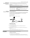
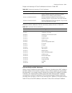
After the above configuration, enter the display command in any view to display the
running of the UDP Helper destination server, and to verify the effect of the
configuration. Enter the
debugging command in User View to debug UDP Helper
configuration.
UDP Helper
Configuration Example
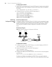
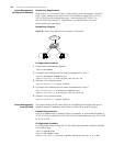
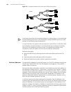
Networking Requirement
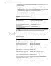
The IP address of VLAN interface 2 on the Switch is 10.110.1.1, which is connected
with network segment 10.110.0.0. Set to relay-forward the broadcast packets with
destination IP of all 1s and destination UDP port 55 in the network segment
10.110.0.0 to the destination server 202.38.1.2.
Networking Diagram
Figure 77 Networking for UDP Helper Configuration
Configuration Procedure
1 Enable UDP Helper function.
[SW5500]udp-helper enable
2 Set to relay-forward the broadcast packets with destination UDP port 55.
[SW5500]udp-helper port 55
3 Set the IP address of the destination server corresponding to VLAN interface 2 as
202.38.1.2.
[SW5500]interface vlan 2
[SW5500-Vlan-interface2]udp-helper server 202.38.1.2
IP Performance
Configuration
IP performance is described in the following section.
Configuring TCP Attributes
TCP attributes that can be configured include:
■ synwait timer: When sending the syn packets, TCP starts the synwait timer. If
response packets are not received before synwait timeout, the TCP connection will
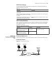
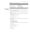
Table 303 Displaying and Debugging UDP Helper Configuration
Operation Command
Display the destination server
corresponding to VLAN interface
display udp-helper server [ interface
vlan-interface vlan_id ]
Enable UDP Helper debugging debugging udp-helper { event | packet [ receive |
send ] }
Disable UDP Helper debugging undo debugging udp-helper { event | packet [
receive | send ] }
Ethernet
Ethernet
Internet
Switch ( UDP Helper )
10.110.0.0
Server
202.38.1.2
10.110.1.1
202.38.0.0
202.38.1.1