


Clustering Configuration Example 613
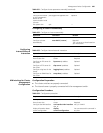
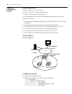
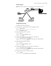
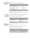
Network diagram
Figure 176 Network diagram for the interfaces of cluster management network
Configuration procedure
Configuring the Switch 5500 switch
1 Enter system view. Specify VLAN 3 as the management VLAN.
<S5500> system-view
System View: return to User View with Ctrl+Z.
[S5500] management-vlan 3
2 Assign port Ethernet 1/0/1 to VLAN 3.
[S5500] vlan 3
[S5500-vlan3] port Ethernet 1/0/1
[S5500-vlan3] quit
3 Configure the IP address of Vlan-interface3 to 192.168.4.30.
[S5500] interface Vlan-interface 3
[S5500-Vlan-interface3] ip address 192.168.4.30 255.255.255.0
[S5500-Vlan-interface3] quit
4 Assign port Ethernet 1/0/2 to VLAN 2.
[S5500] vlan 2
[S5500-vlan2] port Ethernet 1/0/2
[S5500-vlan2] quit
5 Configure the IP address of Vlan-interface2 to 192.168.4.22.
[S5500] interface Vlan-interface 2
[S5500-Vlan-interface2] ip address 192.168.4.22 255.255.255.0
[S5500-Vlan-interface2] quit
6 Configure Vlan-interface2 as the NM interface.
[S5500] cluster
[S5500-cluster] nm-interface Vlan-interface 2
Port e1/0/2)
VLAN 2 VLAN 2
FTP Sever
(IP Address 192.168.4.3
)
(IP Address192.168.4.22
S3526E
(IP Address 192.168.4.30
Port e1/0/1)
S2403
FTP Sever
(IP Address 192.168.4.3
)
S3900
S3526E S2403
Port e1/0/2)
VLAN 2 VLAN 2
FTP Sever
(IP Address 192.168.4.3
)
(IP Address192.168.4.22
S3526E
VLAN 3
(IP Address 192.168.4.30
Port e1/0/1)
S2403
FTP Sever
(IP Address 192.168.4.3
)
S3900
S3526E S2403
Port e1/0/2)
VLAN 2 VLAN 2
FTP Sever
(IP Address 192.168.4.3
)
(IP Address192.168.4.22
S3526E
(IP Address 192.168.4.30
Port e1/0/1)
S2403
FTP Sever
(IP Address 192.168.4.3
)
S3900
S3526E S2403
Port e1/0/2)
VLAN 2 VLAN 2
FTP Sever
(IP Address 192.168.4.3
)
(IP Address192.168.4.22
S3526E
VLAN 3
(IP Address 192.168.4.30
Port e1/0/1)
S2403
FTP Sever
(IP Address 192.168.4.3
)
S3900
S3526E S2403