


Static Routes 223
Displaying and Debugging Static Routes
After you configure static and default routes, execute the
display command in any
view to display the static route configuration, and to verify the effect of the
configuration.
Example: Typical Static
Route Configuration
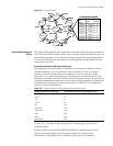
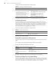
Networking Requirements
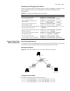
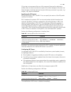
The masks of all the IP addresses shown in Figure 54 are 255.255.255.0. All the hosts
or switches must be interconnected in pairs by configuring static routes.
Networking Diagram
Figure 54 Networking diagram of the static route configuration example
Configuration procedure
1 Configure the static route for Ethernet Switch A
[Switch A]ip route-static 1.1.3.0 255.255.255.0 1.1.2.2
[Switch A]ip route-static 1.1.4.0 255.255.255.0 1.1.2.2
[Switch A]ip route-static 1.1.5.0 255.255.255.0 1.1.2.2
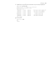
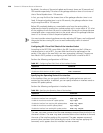
Table 201 Displaying and debugging the routing table
Operation Command
View routing table summary display ip routing-table
View routing table details display ip routing-table verbose
View the detailed information of a
specific route
display ip routing-table ip_address [
mask ] [ longer-match ] [ verbose ]
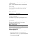
View the route information in the
specified address range
display ip routing-table ip_address1
mask1 ip_address2 mask2 [ verbose ]
View the route filtered through specified
basic access control list (ACL)
display ip routing-table acl acl_number
[ verbose ]
View the route information that through
specified ip prefix list
display ip routing-table ip-prefix
ip_prefix_name [ verbose ]
View the routing information found by
the specified protocol
display ip routing-table protocol
protocol [ inactive | verbose ]
View the tree routing table display ip routing-table radix
View the statistics of the routing table display ip routing-table statistics
A
B
C
Host 1.1.5.1
1.1.5.2/24
1.1.2.2/24
1.1.2.1/24
1.1.1.2/24
Host 1.1.1.1
Host 1.1.4.2
1.1.3.1/24
1.1.3.2/24
1.1.4.1/24
Switch A
Switch B
Switch C