


192 CHAPTER 13: MSTP CONFIGURATION
4 Configure Switch D.
a Enter MST region view.
<S5500> system-view
System View: return to User View with Ctrl+Z.
[S5500] stp region-configuration
b Configure the MST region.
[S5500-mst-region] region-name example
[S5500-mst-region] instance 1 vlan 10
[S5500-mst-region] instance 3 vlan 30
[S5500-mst-region] instance 4 vlan 40
[S5500-mst-region] revision-level 0
c Activate the settings of the MST region.
[S5500-mst-region] active region-configuration
BPDU Tunnel
Configuration
Example
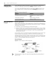
Network requirements
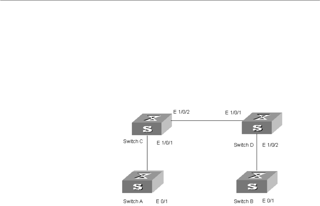
■ Two Switch 5500 switches, Switch C and Switch D shown in Figure 46, operate as
the access devices of the operator’s network.
■ Two S2000 series switches, Switch A and Switch B shown in Figure 46, are used as
the access devices of the user network.
■ Switch C and Switch D are connected to each other through two ports that are
configured as trunk ports. The BPDU tunnel function is enabled in system view to
allow transparent transmission of BPDUs over the operator’s network.
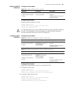
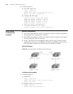
Network diagram
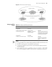
Figure 46 Network diagram for BPDU tunnel configuration
Configuration procedure
1 Configure Switch A.
a Enable RSTP.
<S5500> system-view
System View: return to User View with Ctrl+Z.
[S5500] stp enable
b Add Ethernet0/1 port to VLAN 10.
[S5500] vlan 10
[S5500-Vlan10] port Ethernet 0/1