


570 CHAPTER 28: SNMP CONFIGURATION
Displaying and
Debugging SNMP
After the above configuration, execute the display command in all views to display
the running of the SNMP configuration, and to verify the effect of the configuration.
Execute the debugging command in User View to debug SNMP configuration.
Table 631 Display and Debug SNMP
SNMP Configuration
Example
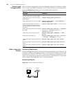
Networking Requirements
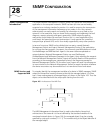
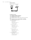
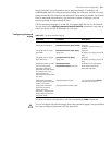
Network Management Station and the Switch are connected using the Ethernet. The
IP address of Network Management Station is 129.102.149.23 and that of the VLAN
interface on the Switch is 129.102.0.1. Perform the following configurations on the
Switch: set the community name and access authority, administrator ID, contact and
Switch location, and enable the Switch to send trap packet.
Networking Diagram
Figure 166 SNMP Configuration Example
Operation Command
Display the modules with trap enabled
and the module with trap not enabled
display snmp-agent trap-list
Display the statistics information about
SNMP packets
display snmp-agent statistics
Display the engine ID of the active device display snmp-agent { local-engineid |
remote-engineid }
Display the group name, the security
mode, the states for all types of views,
and the storage mode of each group of
the Switch.
display snmp-agent group [ group-name ]
Display the names of all users in the group
user table
display snmp-agent usm-user [ engineid
engineid ] [ group groupname ] [
username username ]
Display the current community name display snmp-agent community [ read |
write ]
Display the current MIB view display snmp-agent mib-view [ exclude
| include | viewname mib-view ]
Display the contact character string of the
system
display snmp-agent sys-info contact
Display the location character string of the
system
display snmp-agent sys-info location
Display the version character string of the
system
display snmp-agent sys-info version
Ethernet
NMS
129.102.0.1
129.102.149.23