


302 CHAPTER 17: NETWORK PROTOCOL OPERATION
Access Management
Configuration Example
Networking Requirements
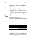
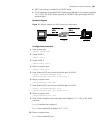
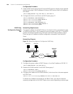
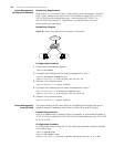
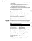
Organization 1 is connected to port 1 of the Switch, and organization 2 to port 2.
Ports 1 and 2 belong to the same VLAN. The IP addresses range 202.10.20.1 to
202.10.20.20 can be accessed from port 1 and the range 202.10.20.21 to
202.10.20.50 from the port 2. Organization 1 and organization 2 cannot
communicate with each other.
Networking Diagram
Figure 76 Networking Diagram for Port Isolation Configuration
Configuration Procedure
1 Enable access management globally.
[SW5500]am enable
2 Configure the IP address pool for access management on port 1.
[SW5500]interface ethernet1/0/1
[SW5500-Ethernet1/0/1]am ip-pool 202.10.20.1 20
3 Add port 1 into isolation group.
[SW5500-Ethernet1/0/1]port isolate
4 Configure the IP address pool for access management on port 2
[SW5500-Ethernet1/0/1]interface ethernt1/0/2
[SW5500-Ethernet1/0/2]am ip-pool 202.10.20.21 30
5 Add port 2 into isolation group.
[SW5500-Ethernet1/0/2]port isolate
Access Management
using the Web
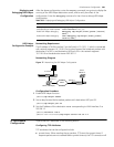
The Security/Authorized IP menu option on the Web interface allows the user to
specify a range of IP addresses that will permit Web, Telnet and SSH access.
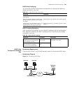
Network Requirements
Enter an IP address and a ‘wildcard’ value. For example, an authorized IP address of
10.10.10.1 with a wildcard of 0.0.0.255 will authorize all addresses from 10.10.10.0
to 10.10.10.254.
Configuration Procedure
To configure this feature using the CLI, the following commands should be entered
from System View:
<SW5500>system-view
[SW5500]acl number 2500
[SW5500-acl-basic-2500]rule 0 permit source 10.10.10.1 0.0.0.255
External
Network
E 0/1
E 0/2