


158 CHAPTER 12: VRRP CONFIGURATION
Configuration procedure
1 Configure Switch A.
a Configure VLAN 2.
<LSW-A> system-view
System View: return to User View with Ctrl+Z.
[LSW-A] vlan 2
[LSW-A-vlan2] port Ethernet 1/0/6
[LSW-A-vlan2] quit
[LSW-A] interface vlan-interface 2
[LSW-A-Vlan-interface2] ip address 202.38.160.1 255.255.255.0
[LSW-A-Vlan-interface2] quit
b Configure VRRP.
[LSW-A] vrrp ping-enable
[LSW-A] interface vlan 2
[LSW-A-Vlan-interface2] vrrp vrid 1 virtual-ip 202.38.160.111
[LSW-A-Vlan-interface2] vrrp vrid 1 priority 110
[LSW-A-Vlan-interface2] vrrp vrid 1 preempt-mode
2 Configure Switch B.
a Configure VLAN 2.
<LSW-B> system-view
System View: return to User View with Ctrl+Z.
[LSW-B] vlan 2
[LSW-B-Vlan2] port Ethernet 1/0/5
[LSW-B-vlan2] quit
[LSW-B] interface vlan-interface 2
[LSW-B-Vlan-interface2] ip address 202.38.160.2 255.255.255.0
[LSW-B-Vlan-interface2] quit
b Configure VRRP.
[LSW-B] vrrp ping-enable
[LSW-B] interface vlan 2
[LSW-B-Vlan-interface2] vrrp vrid 1 virtual-ip 202.38.160.111
[LSW-B-Vlan-interface2] vrrp vrid 1 preempt-mode
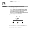
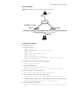
The IP address of the default gateway of Host A can be configured to be
202.38.160.111.
Normally, Switch A functions as the gateway, but when Switch A is turned off or
malfunctions, Switch B will function as the gateway instead.
Configure Switch A to operate in preemptive mode, so that it can resume its gateway
function as the master switch after recovery.
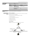
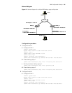
VRRP Tracking Interface
Example
Network requirements
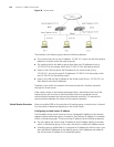
Even when Switch A is still functioning, Switch B can function as a gateway when the
interface on Switch A and connecting to Internet does not function properly. This can
be implemented by enabling the VLAN interface tracking function.
The VRRP backup group ID is set to 1, with additional configurations of authorization
key and timer.