


164 CHAPTER 13: MSTP CONFIGURATION
Basic MSTP
Terminologies
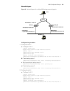
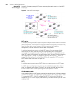
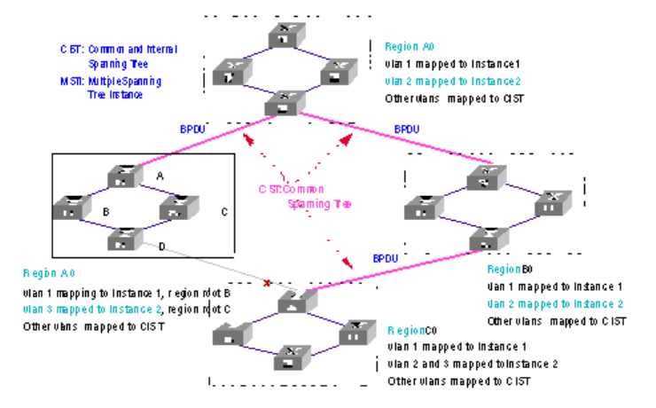
Figure 42 illustrates primary MSTP terms (assuming that each switch in it has MSTP
employed).
Figure 42 Basic MSTP terminologies
MST region
A multiple spanning tree (MST) region comprises multiple switches and the connected
network segments. The switches are all MSTP-enabled and physically connected. They
have the same region name, the same VLAN-to-spanning tree mapping
configuration, and the same MSTP revision level configuration.
A switched network can contain multiple MST regions. You can group multiple
switches into one MST region by using the corresponding MSTP configuration
commands. For example, as shown in Figure 42, all switches in region A0 have the
same MST region configuration: the same region name, the same VLAN-to-spanning
tree mapping (that is, VLAN 1 is mapped to spanning tree instance 1, VLAN 2 is
mapped to spanning tree 2, and the other VLANs are mapped to CIST), the same
MSTP revision level (not shown in Figure 42).
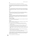
MSTI
A multiple spanning tree instance (MSTI) refers to a spanning tree in a MST region.
In a MST region, multiple spanning trees can be established independent of each
other. For example, each region in Figure 42 can contain multiple spanning trees,
known as MSTIs. Each of these spanning trees corresponds to a VLAN.
VLAN mapping table
VLAN mapping table is a MST region attribute for describing how VLANs are mapped
to MSTIs. For example, the VLAN mapping table of region A0 in Figure 42says: VLAN
1 is mapped to MSTI 1; VLAN 2 is mapped to MSTI 2; and the other VLANs are
mapped to CIST. In an MST region, load balancing is achieved according to the VLAN
mapping table.