


166 CHAPTER 13: MSTP CONFIGURATION
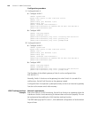
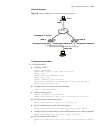
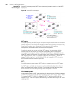
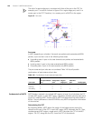
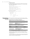
The role of a region edge port is consistent with that of the port in the CIST. For
example, port 1 on switch A shown in Figure 43 is a region edge port, and it is a
master port in the CIST. Therefore, it is a master port in all MSTIs in the region.
Figure 43 Port roles
Port state
In MSTP, depending on whether it forwards user packets and receives/sends BPDU
packets, a port can be in one of the following three states:
■ Forwarding state: A port in this state forwards user packets and receives/sends
BPDU packets.
■ Learning state: A port in this state receives/sends BPDU packets.
■ Discarding state: A port in this state receives only BPDU packets.
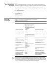
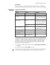
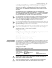
The port states and port roles are not correlated. Table 140 lists all possible
combinations of port states and port roles.
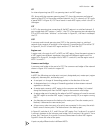
Fundamentals of MSTP MSTP divides a network into multiple MST regions at Layer 2 and calculates the CST
of these MST regions. In each MST region, it generates multiple spanning trees, each
of which is called an MSTI. Similar to RSTP, MSTP calculates spanning trees based on
BPDUs. The only difference is that MSTP BPDUs carry MSTP configuration information
of the switches.
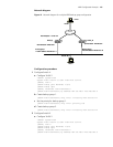
Determining the CIST
By comparing BPDUs, MSTP selects the switch of the highest priority across the
network as the root of the CIST. In each MST region, MSTP calculates the ISTs. Then,
considering each MST region a single switch, MSTP calculates the CST of the MST
regions. The CST, along with the ISTs, forms the CIST of the network.
Table 140 Combinations of port states and port roles
Port state
Port role
Root port/Master
port
Designated
port
Region
edge port
Alternate
port
Backup port
Forwarding x x x - -
Learning x x x - -
Discarding x x x x x