


Auto Detect Implementation in VRRP 535
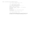
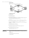
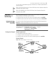
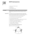
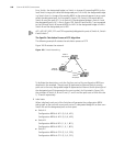
Network diagram
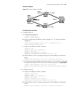
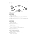
Figure 157 Network diagram for VRRP
Configuration procedure
1 Configure Switch B.
a Create detecting group 9.
<S5500 B> system-view
[S5500 B] detect-group 9
b Specify to detect the reachability of the IP address 10.1.1.4, setting the detect
number to 1.
[S5500 B-detect-group-9] detect-list 1 ip address 10.1.1.4
[S5500 B-detect-group-9] quit
c Assign an IP address to VLAN 1 interface.
[S5500 B] vlan 1
[S5500 B-vlan1] port ethernet1/0/1
[S5500 B-vlan1] quit
[S5500 B] interface vlan-interface 1
[S5500 B-vlan-interface1] ip address 192.168.1.2 24
d Enable VRRP on VLAN 1 interface and assign a virtual IP address to the backup
group.
[S5500 B-vlan-interface1] vrrp vrid 1 virtual-ip 192.168.1.10
e Set the backup group preference value of switch B to 110, and specify to decrease
the preference value by 20 when the result of detecting group 9 is unreachable.
[S5500 B-vlan-interface1] vrrp vrid 1 priority 110
[S5500 B-vlan-interface1] vrrp vrid 1 track detect-group 9 reduced
20
2 Configure Switch D.
a Assign an IP address to VLAN 1 interface.
<S5500 D> system-view
[S5500 D] vlan 1
[S5500 D-vlan1] port ethernet1/0/1
[S5500 D-vlan1] quit
[S5500 D] interface vlan-interface 1
[S5500 D-vlan-interface1] ip address 192.168.1.3 24
b Enable VRRP on VLAN 1 interface and assign a virtual IP address to the backup
group.
[S5500 D-vlan-interface1] vrrp vrid 1 virtual-ip 192.168.1.10
192.168.1.2
20.1.1.2
10.1.1.3
10.1.1.4
Switch C
192.168.1.1/24
192.168.1.2/24
192.168.1.3/24
20.1.1.3/24
10.1.1.3/24
Et hernet 1/0/1
10.1.1.4/24
Et hernet 2/0/1
Switch A
Switch B
Switch C
Switch D
VLAN 1
20.1.1.4/24
VLAN 1
VLAN 1
VLAN 1
192.168.1.2
20.1.1.2
10.1.1.3
10.1.1.4
Switch C
192.168.1.1/24
192.168.1.2/24
192.168.1.3/24
20.1.1.3/24
10.1.1.3/24
Et hernet 1/0/1
10.1.1.4/24
Et hernet 2/0/1
Switch A
Switch B
Switch C
Switch D
VLAN 1
20.1.1.4/24
VLAN 1
VLAN 1
VLAN 1