


234 CHAPTER 16: IP ROUTING PROTOCOL OPERATION
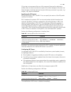
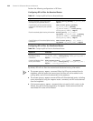
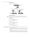
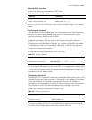
Networking Diagram
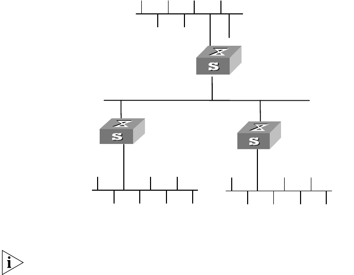
Figure 55 RIP configuration networking
Configuration Procedure
The following configuration only shows the operations related to RIP. Before
performing the following configuration, please make sure the Ethernet link layer can
work normally.
1 Configure RIP on Switch A
[Switch A]rip
[Switch A-rip]network 110.11.2.0
[Switch A-rip]network 155.10.1.0
2 Configure RIP on Switch B
[Switch B]rip
[Switch B-rip]network 196.38.165.0
[Switch B-rip]network 110.11.2.0
3 Configure RIP on Switch C
[Switch C]rip
[Switch C-rip]network 117.102.0.0
[Switch C-rip]network 110.11.2.0
Troubleshooting RIP The Switch 5500 cannot receive the update packets when the physical connection to
the peer routing device is normal.
■ RIP does not operate on the corresponding interface (for example, the undo rip
work
command is executed) or this interface is not enabled through the network
command.
■ The peer routing device is configured to be in the multicast mode (for example,
the
rip version 2 multicast command is executed) but the multicast mode has
not been configured on the corresponding interface of the local Ethernet Switch.
Ethernet
Network address:
110.11.2.2/24
Network address:
117.102.0.0/16
Network address:
196.38.165.0/24
Interface address:
110.11.2.1/24
Interface address:
117.102.0.1/16
Interface address:
155.10.1.1/24
Network address:
155.10.1.0/24
Interface address:
196.38.165.1/24
SwitchA
SwitchB
SwitchC