AMD Geode™ LX Processors Data Book 197
CPU Core Register Descriptions
33234H
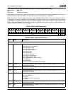
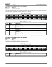
5.5.2.107 Bus Controller Debug Registers 0 through 3 MSRs
Each of these registers specifies an address that must match the physical address currently in the bus controller in order to
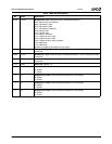
trigger the breakpoint. BDR7 is used to enable and specify the type of BDR0-BDR3. If a breakpoint is configured as a mem-
ory breakpoint, the address is matched on a QWORD granularity. If a breakpoint is configured as an I/O or MSR breakpoint,
the address is matched based on all 32 bits.
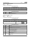
Bus Controller Debug Register 0 MSR (BDR0_MSR)
Bus Controller Debug Register 1 MSR (BDR1_MSR)
Bus Controller Debug Register 2 MSR (BDR2_MSR)
Bus Controller Debug Register 3 MSR (BDR3_MSR)
MSR Address 00001970h
Typ e R /W
Reset Value 00000000_00000000h
MSR Address 00001971h
Typ e R /W
Reset Value 00000000_00000000h
MSR Address 00001972h
Type R /W
Reset Value 00000000_00000000h
MSR Address 00001973h
Type R /W
Reset Value 00000000_00000000h
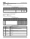
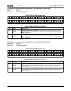
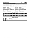
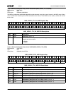
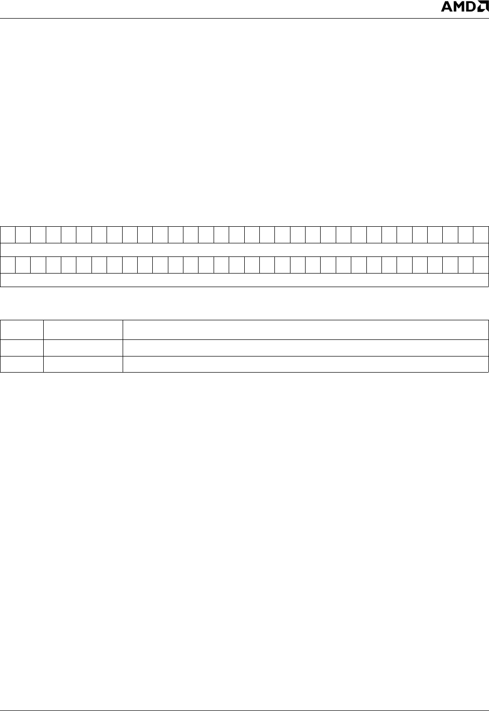
BDRx_MSR Register Map
63 62 61 60 59 58 57 56 55 54 53 52 51 50 49 48 47 46 45 44 43 42 41 40 39 38 37 36 35 34 33 32
RSVD
313029282726252423222120191817161514131211109876543210
PHYS_ADDR
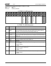
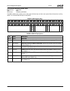
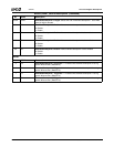
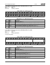
BDRx_MSR Bit Descriptions
Bit Name Description
63:32 RSVD Reserved. (Default = 0)
31:0 PHYS_ADDR Address Match Value for BDRx. (Default = 0)


